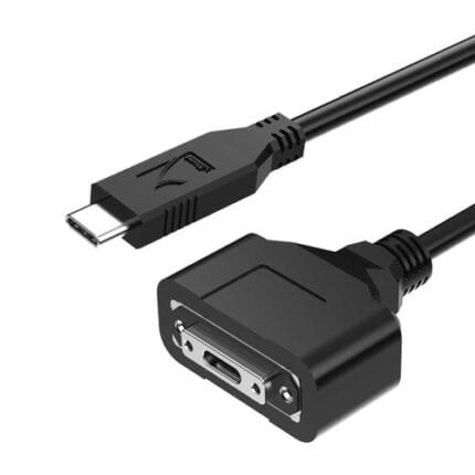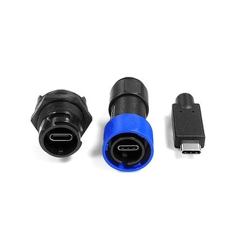
SPE Bulkhead Panel Connector for 10BASE-T1L Field Devices
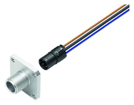
An SPE bulkhead panel connector brings 10BASE-T1L single pair Ethernet and Power over Data Line into a field device box through one sealed penetration. IEC 63171-6 mating face or M8 coupling, front or rear mounting. The cut-out is smaller and the termination is faster than a four-pair Ethernet entry.
Last updated: 13 September 2026
Overview
An SPE bulkhead panel connector lets a 10BASE-T1L link enter a sensor junction box, a building automation panel or a process skid without a field-made gland. Two contacts and a shield replace the four pairs of a conventional Ethernet run, which reduces the hole size, the termination time and the amount of copper that has to be dressed inside a small enclosure.
Key Specifications
| Interface | Two contacts plus shield, 10BASE-T1L single pair Ethernet |
|---|---|
| Mating face | IEC 63171-6 mating face or M8 threaded coupling |
| Power | Power over Data Line, 4 A / 60 V DC – design target, confirm |
| Ingress rating | IP66 / IP67 / IP68 – design target, pending test |
| Mounting | Front or rear mounting |
| Operating temperature | -40 C to +85 C – supplier datasheet confirmation pending |
| Applications | Field device enclosures, building automation panels, sensor junction boxes, process skids |
| Cut-out | Design target – confirm against supplier drawing before cutting |
| Pairing | Designed to pair with single pair Ethernet cordsets |
| Shield transfer | Screen bonded at the shell and referenced to the enclosure wall |
| Topology note | Reach and speed trade against each other; segment rules apply |
10BASE-T1L to the field device: what actually changes
10BASE-T1L is defined in IEEE 802.3cg and carries 10 Mbit/s over a single twisted pair, with the reach commonly quoted up to 1000 m. Power over Data Line, specified in IEEE 802.3bu, puts DC onto the same pair, which removes the separate power drop to the device. For the panel builder the practical consequences are these:
| Four-pair Ethernet to a field device | 10BASE-T1L through a bulkhead | |
|---|---|---|
| Conductors terminated | Eight, in four pairs | Two, in one pair |
| Cable diameter and weight | Large, stiff, awkward in a small box | Thin and light, easy to dress |
| Enclosure penetration | Bigger gland, bigger hole | Small penetration, small hole |
| Power | Separate drop, or PoE with its own rules | PoDL on the same pair |
| Reach | 100 m per channel, then a switch | Up to 1000 m class without a switch in between |
| Termination time | Higher, and higher still in a small enclosure | Two contacts and a shield |
| Where it loses | Standardized everywhere, huge installed base | Segment and topology rules are different; check them before laying out spurs |
Which mating face: IEC 63171-6 or M8
Two coupling styles are offered, and the choice usually comes down to what is already on site.
| IEC 63171-6 mating face | M8 threaded coupling | |
|---|---|---|
| Also called | The T1 Industrial interface | M8 sensor-style coupling |
| Contacts | Two, with a defined symmetrical mating face | Two, in an M8 shell |
| Best for | New SPE infrastructure built to the standard | Installations already built on M8 sensor wiring |
| Advantage | The defined SPE interface; IP20 and IP67 versions share the mating face | Reuses existing M8 panel cut-outs and harnesses |
| Confirm | The edition of the standard your project specifies | Whether your cordsets are M8 or T1 |
The same mating face is used across the IP20 and the IP65/67 housing styles, which is worth knowing: a laptop with an IP20 lead can be plugged into an IP67 device end for parameterization without an adapter. Single pair Ethernet is still a moving target on editions, so state which one your project works to when you enquire.
Power over Data Line: size it, do not assume it
PoDL is the reason many field devices move to a single pair, so the current and voltage figures matter as much as the data path. The 4 A at 60 V DC figure is a design target from competitor published data and needs confirmation against the supplier datasheet before it is used to size a load. It is not interchangeable with a PoE class figure, and the power actually delivered depends on the loop resistance of the run: give us the length and the load and we will check the drop rather than quoting a number off a listing.
Cut-out, mounting direction and sealing
Front mounting suits thin enclosure walls and keeps the gasket on the accessible side. Rear mounting hides the flange behind the wall and is preferred where the panel face has to stay flat for wiping or for a label. The cut-out diameter and the hardware dimensions are design targets: confirm them before cutting a coated enclosure, and check that the wall thickness at the mounting point falls inside the range the hardware clamps.
Sealing depends on the gasket seating on a flat, deburred land. On cast or molded boxes with a draft angle, face the mounting area flat before fitting, or use a sealing washer on the inside face. Keep the pair twist right up to the termination – a couple of centimeters of untwisted conductor at the contacts destroys the balance that gives the link its reach.
Typical applications for this SPE bulkhead panel connector
- Field device enclosures and sensor junction boxes on a process skid
- Building automation panels feeding HVAC actuators, valve drives and room sensors
- Lighting control segments where each luminaire becomes an addressable node
- Access control and metering points spread along a corridor or a riser
- IIoT sensor drops that were previously on a fieldbus, paired with our 10BASE-T1L Patch Cord for Single Pair Ethernet
- Panel builders adding an SPE service port next to an existing RJ45 port
What we will not quote without a datasheet
Reach, conductor size, current and voltage ratings, temperature range, mating cycles and the IP66, IP67 and IP68 targets all come from published competitor data and are pending confirmation. The reach figure in particular is a property of the cable and the segment, not of the receptacle.
How to specify your build
- Mating face – IEC 63171-6 or M8, and the edition you work to.
- Mounting direction – front or rear, plus the wall thickness.
- Cut-out off your enclosure drawing, or off the existing hardware.
- Power budget – the load in watts and the run length, so the drop can be checked.
- Inside termination – solder, PCB or a molded tail, and its length.
- Ingress target – IP66, IP67 or IP68, and whether it is tested on the batch.
- Quantity, and whether this is a prototype or a production order.
Workmanship and testing
Builds here run under ISO 9001 to IPC/WHMA-A-620 Class 3 workmanship, across 32 to 12 AWG. Every assembly is tested for continuity and pinout before packing. Seal checking on the production batch can be quoted when the specification includes an ingress rating.
Custom builds and ordering
A prototype lot of 5 pcs ships in 3 working days; series orders start at 500 pcs and ship 14 working days after sample approval. We hold 100 sets of mold tooling in house, so a standard body needs no tooling time and a new one adds about 10 working days. OEM and ODM builds go out under your part number and label, with material certificates and first-article reports on request.
Related single pair and panel hardware
- 10BASE-T1L Patch Cord for Single Pair Ethernet, T1 Industrial or M8
- 10BASE-T1L Screw Lock Cable with Sealed M8 or IEC 63171-6 Couplings
- SPE M12 Hybrid Single-Pair Ethernet + Power Cable (IEC 63171-7)
- Single Pair Ethernet Cable in M8 and M12 Shells for Sensor Runs
- M12 Hybrid SPE Cable for Actuators and Valve Islands
- Control Cabinet Service Interface with RJ45 and USB-C Front Plate
Full ranges: panel mount cable, circular M8 and M12 cable and Ethernet patch cords.
Frequently Asked Questions
Is PoDL the same as PoE?
No. PoE uses two or four pairs and its own classes; PoDL is defined in IEEE 802.3bu and puts power on a single pair. The figures are not interchangeable and the delivered power depends on the loop.
Can I reuse my existing M8 panel cut-outs?
Usually yes for the M8 coupling version, which is exactly why it is offered. Confirm the diameter and the wall thickness against the supplier drawing before you rely on it.
How far will a 10BASE-T1L link run?
Reach up to 1000 m is the commonly quoted figure for the standard, but it is a property of the cable, the conductor size and the segment, not of the receptacle. Tell us the run and we will check it.
Do I need a shielded construction?
For industrial runs, yes in most cases, and the screen should be bonded at the connector shell and referenced to earth at one point at least. Keep the run out of the same conduit as drive output.
| Interface | Two contacts plus shield, 10BASE-T1L single pair Ethernet |
|---|---|
| Mating face | IEC 63171-6 mating face or M8 threaded coupling |
| Power | Power over Data Line |
| Ingress rating | IP66 / IP67 / IP68 class |
| Mounting | Front or rear mounting |
| Operating temperature | -40 C to +85 C class |
| Applications | Field device enclosures, building automation panels, sensor junction boxes, process skids |
| Cut-out | Design target – confirm against supplier drawing before cutting |
| Pairing | Designed to pair with single pair Ethernet cordsets |
| Shield transfer | Screen bonded at the shell and referenced to the enclosure wall |
| Topology note | Reach and speed trade against each other; segment rules apply |
Related products