USB3 Vision Camera Cable with Locking Screws for Machine Vision
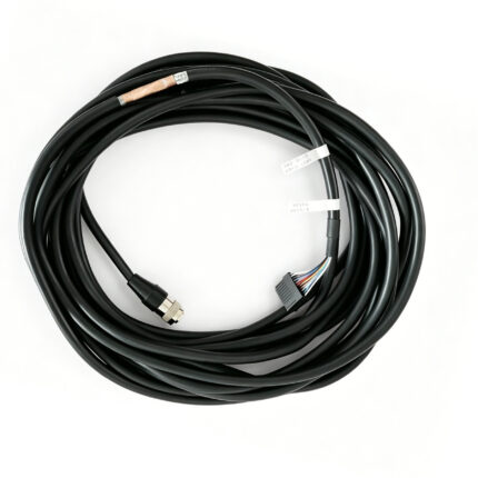
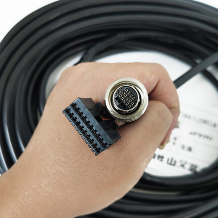
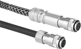
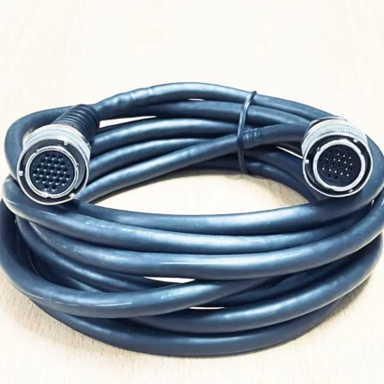
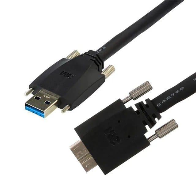
A USB3 vision camera cable with captive thumb screws at the host end and the camera end, so the connection stays seated next to a conveyor or an indexing table. Double shielded high-speed pairs, 0.5 m to 10 m, with a drag-chain grade option.
Overview
Machine vision cameras sit next to conveyors, indexing tables and robot cells, and a standard USB connector held in only by friction will walk out over time. The symptom is intermittent: frames drop, the camera re-enumerates, and the fault gets blamed on the software. A usb3 vision camera cable in this range uses captive thumb screws on the host side and the camera side so the connection stays seated.
Key Specifications
| Product type | USB3 Vision camera cable with screw locking |
|---|---|
| Host end | USB-A or USB-C with captive thumb screws |
| Camera end | Locking screw shell, USB 3.2 type B or USB-C |
| Data rate | 5 Gbps to 7 m, 10 Gbps to 5 m – design targets, to be confirmed |
| Outside diameter | 6.2 mm – to be confirmed |
| Shielding | Double layer, foil plus braid over the high-speed pairs |
| Length range | 0.5 m to 10 m |
| Option | Drag-chain grade construction |
What the standard asks for, and what the rate means
USB3 Vision is the interface standard for machine vision cameras over USB, sitting on top of the USB 3.x physical layer. The rates below are the industry definitions; the practical limit on any given installation is set by the length, the host controller and the camera silicon together.
| Class | Defined signaling rate | Quoted passive reach in this class |
|---|---|---|
| USB 3.2 Gen 1 | 5 Gbps | Up to around 7 m |
| USB 3.2 Gen 2 | 10 Gbps | Up to around 5 m |
| Beyond that | – | Use an active or optical assembly, not a longer passive lead |
Both reach figures are design targets here, pending bit error and eye diagram testing on finished assemblies, because passive copper reach is the most over-stated number in this category. The honest answer for a given installation is a tested length rather than a printed one.
Where locking screws are required
| Installation | Why friction retention fails | What to specify |
|---|---|---|
| Camera on a conveyor or indexing table | Continuous vibration walks the plug out | Captive thumb screws both ends |
| Camera on a moving gantry | Cable drag pulls on the plug every cycle | Locking screws plus drag-chain grade construction |
| Host PC in a cabinet with the door opening | Loops of cable flex and lever the plug | Screw-lock shell at the host end as well |
| Camera on a bench test rig | Frequent reconnection, no vibration | A standard lead is usually fine |
Shielding and the noise environment
The high-speed pairs carry foil plus braid, applied over the pairs rather than as a token overall screen, because the failure mode in a cell is not a broken conductor but a noisy one. Frames drop or corrupt, the camera re-enumerates, and the fault looks like software. Two routing rules matter as much as the shielding itself: keep the run away from drive and motor cables, and never coil the surplus – a coil of high-speed cable sitting next to a drive cabinet is a reliable way to lose frames, and it is the first thing we check when a customer reports dropped images.
Selecting a length
- Measure the installed route, not the straight-line distance.
- Add service slack at the camera end only, so the camera can be removed without re-pulling the cable.
- Do not coil the excess. Cut to length instead.
- Check the rate at the length you need, because the two are traded against each other.
If a run genuinely needs more than 10 m, an active or optical assembly is the correct answer rather than a longer passive lead. The passive copper limit does not move with a better jacket.
Drag-chain grade: specify it at enquiry stage
A drag-chain version is offered where the camera moves or the cable runs on a gantry. That changes the jacket compound and the strain relief design rather than the connector, so it has to be specified at enquiry stage and cannot be added later. Tell us the travel and the cycle rate and we will size the construction accordingly rather than quoting a static cable into a dynamic job.
Workmanship and testing
USB3 Vision Camera builds are made to IPC/WHMA-A-620 Class 3 workmanship inside an ISO 9001 system, over a 32 to 12 AWG range. continuity and pinout are verified on each USB3 assembly before packing, and seal checking is quoted whenever an ingress rating is on the drawing.
Every production run can ship with RoHS and REACH declarations and the electrical report agreed at quotation; see certifications and material declarations. UL styles and other named approvals are built to drawing: we source to the style you specify and document it, rather than asserting a listing we do not hold. This build follows the continuous-flex practice documented under continuous-flex construction and flex-life testing, where cycle targets are agreed before the first part is made. The wider context is covered under cable assemblies for test and measurement. Tooling is quoted separately, cut in-house rather than brokered out, and owned by you.
Custom builds and ordering
For USB3 Vision Camera builds, prototypes run from 1 to 50 pcs with a 3 working day turnaround. Volume orders begin at 500 pcs and ship 14 working days after sample approval. OEM and ODM USB3 work ships under your part number and labeling, and material certificates and first-article reports can be supplied. We hold 100 sets of mold tooling in house, so a standard body needs no tooling time and a new one adds about 10 working days.
Typical applications for this usb3 vision camera cable
- Conveyor and indexing table inspection stations where vibration is continuous
- Gantry mounted cameras, alongside our CoaXPress machine vision cable on higher rate lines
- Cell cameras terminated at an industrial panel using our USB Type-C to M12 8-pin industrial cable
- Host side extension with our screw-lock USB 3.0 Type-A extension cable
- Gigabit installations running alongside a Cat6A RJ45 screw-lock GigE Vision cable
Related assemblies
- CoaXPress Machine Vision Cable Assembly for CXP-12 Links
- USB Type-C to M12 8-Pin Industrial Cable
- Screw-Lock USB 3.0 Type-A Extension Cable
- Cat6A RJ45 Screw-Lock GigE Vision Cable
- Cat6A S/FTP GigE Vision Screw-lock Cable for Drag Chain
- USB-C Screw Locking Cable, Side or Top
Full range: screw-lock molded cables.
Frequently Asked Questions
My camera drops frames but the software logs nothing. Why?
Usually the connector or the routing, not the camera. Check for a plug that has walked out, and for a coil of surplus cable sitting next to a drive cabinet.
Can I have 10 Gbps at 10 m?
Not on a passive copper assembly. The quoted figures are 10 Gbps to around 5 m and 5 Gbps to around 7 m, and beyond that you want an active or optical build.
Can I add the drag-chain version later?
No. It changes the jacket compound and the strain relief design, so it has to be specified at enquiry stage.
What is the minimum order?
For USB3 Vision Camera builds, prototypes run from 1 to 50 pcs with a 3 working day turnaround. Volume orders begin at 500 pcs and ship 14 working days after sample approval.
| Product type | USB3 Vision camera cable with screw locking |
|---|---|
| Host end | USB-A or USB-C with captive thumb screws |
| Camera end | Locking screw shell, USB 3.2 type B or USB-C |
| Data rate | 5 Gbps to 7 m, 10 Gbps to 5 m – design targets, to be confirmed |
| Outside diameter | 6.2 mm – to be confirmed |
| Shielding | Double layer, foil plus braid over the high-speed pairs |
| Length range | 0.5 m to 10 m |
| Option | Drag-chain grade construction |