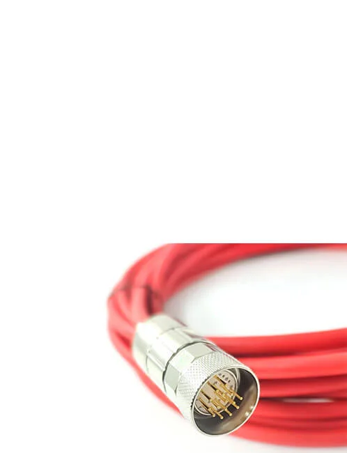
Custom Industrial Robot Wire Harness
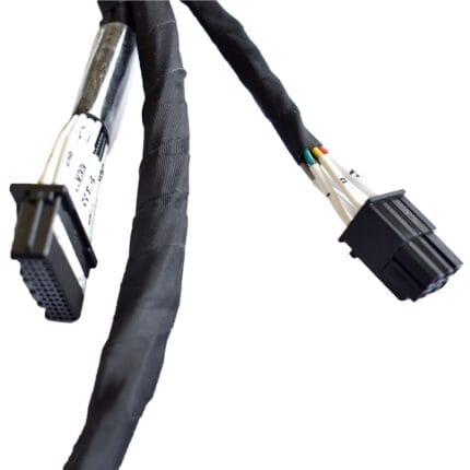
A custom industrial robot wire harness built to your routing, branch points and flex-life requirement, with power, encoder, brake and air tube cores in one assembly.
Overview
A robot harness almost never fails in the middle of a straight run. It fails at a branch, at a clamp, or at the point where the arm twists. A custom industrial robot wire harness has to survive millions of cycles inside a space that gets smaller every time the machine builder adds a function, so most of the engineering is about where the movement goes and where the strain has to stop. We build to your routing, your branch points and your flex requirement, from a drawing or from a sample of the harness you are replacing.
What we build
One harness usually carries four or five very different circuits, and they are built together because they have to move together.
| Circuit | Typical construction | What it needs from the build |
|---|---|---|
| Motor power | The largest conductors in the bundle, sized per your drive rating | Fine-strand conductors and short lay lengths, and a clamp that grips without crushing the insulation |
| Encoder feedback | Screened twisted pairs, sometimes with a separate clock pair | Individual pair screening, 360-degree shield termination at the drive end, and separation from the power cores |
| Brake | Two cores, usually switched DC | Kept away from the encoder pairs or screened on its own, so the release pulse does not land on the feedback lines |
| Pneumatic | Polyurethane or nylon tube running alongside the copper | Its own bend radius, and a branch that lets the tube bend without kinking |
| Vision and fieldbus | Coax, or a Cat5e or Cat6 data pair | Room in the branch, and a screen path that the breakout does not interrupt |
Where a robot harness actually fails
Five places account for most of the harnesses we are asked to re-make, and they exist because a six-axis industrial robot moves its own wiring in more than one direction at the same time.
| Failure point | What you see | How we address it |
|---|---|---|
| Torsion at the outer axes | Conductors broken inside a jacket that looks intact | Torsion-rated construction with a low-friction wrap and a lay direction that lets the bundle unwind instead of binding |
| The branch or breakout | Cracked molding, or a leg pulling out of the trunk | Molded breakouts rather than taped ones, with the branch angle set to the real routing |
| Strain relief at the connector | Intermittent contact that becomes an open circuit | Overmolded strain relief that clamps the jacket behind the flex point, not the conductors |
| Abrasion against the casting | Jacket worn through at one fixed point | Braided sleeving or a conduit section over that run, plus clamps at the right spacing |
| Encoder pair beside power | Position errors and drive faults that come and go | Individual pair foil and physical separation inside the bundle |
| An overfilled carrier | Cables jamming and creasing inside the drag chain | Round-profile construction sized to the carrier, layed up rather than bunched |
Almost none of these is a material defect. They are geometry problems: something is bending where it was never meant to bend, or rubbing where nothing was protecting it. That is also why a harness copied from a photograph usually fails in the same place as the one it replaced.
Branches, fixing and routing
The branch layout is what makes one harness fit first time and the next one impossible to install. We need the breakout positions measured along the trunk, the length of each leg, and the angle each leg leaves at. Where the harness runs along an arm or through a casting, tell us the clamp positions and we will place the fixing points to match, because a clamp in the wrong place turns a flexing run into a fatigue test. Heat-shrink markers, printed labels and a build sheet are standard on production orders.
What we need from you
- A drawing, a sample, or both — a sample is often faster, because we can measure the branch positions instead of guessing at them.
- The circuit list — how many power cores, how many encoder pairs, whether there is a brake, and whether an air tube runs with them.
- Connector and termination schedule — part numbers, or the mating halves, for every end.
- Motion — fixed, drag chain, or torsion, and the axis each section is mounted on.
- Branch positions and lengths, measured on the machine or off the old harness.
- Environment — cutting oil, coolant, weld spatter, chips, vacuum or cleanroom.
- Screening — which pairs, and where each screen terminates.
- Quantity, and whether you need prototypes before the production release.
How the build runs
- Review — we read the drawing or measure the sample, and come back with any branch or bend radius that will not build.
- Fixture and tooling — a layout board is made to your branch positions, so unit one and unit five hundred are the same length.
- Prototype — from 1 to 50 pcs, shipped in 3 working days.
- Fit check — you install it on the arm and cycle it.
- Production — 14 working days from approval, on four assembly lines in Longgang, Shenzhen.
Tooling and lead time
Around 100 sets of mold tooling are held in house, so common connector bodies and strain reliefs need no tooling time, and a new overmold body adds about 10 working days. Prototypes start from 1 to 50 pcs and ship in 3 working days. Production starts at MOQ 500 pcs and ships 14 working days after approval. Four production lines and about 40 assembly staff give us annual capacity of roughly one million pieces. We can also hold a layout board for your part number between repeat orders, so the next release does not start from zero.
Inspection and testing
Assembly and inspection follow IPC/WHMA-A-620 Class 3 workmanship criteria under our ISO 9001 quality management system. Every unit gets 100% continuity and pinout testing before packing, which on a mixed harness means every power core, every encoder pair and the brake circuit, not just a sample. Pull testing on terminations, flex cycling and shield continuity checks are quoted per order. Conductors from 32 to 12 AWG can be mixed in one bundle. Cycle-life figures quoted for a cable construction are the industry values for that construction; the figures your harness is built and verified to are the ones stated on your drawing.
Typical projects for this custom industrial robot wire harness
- Full arm harness for a six-axis welding or handling cell, power and encoder in one trunk
- Collaborative robot arm wiring with a drag-chain jacket — see our cobot arm cable harness with drag-chain jacket
- Torsion sections at the outer axes — robot torsion resistant cable and hybrid robot torsion cable
- Encoder looms replacing a worn original, alongside our encoder feedback cable
- Drive-to-motor sets built with our custom servo motor cable assembly and hybrid servo cable
- Tool-changer and end-of-arm sections, where a sealed circular connector is used at the interface — M12 M-coded motor cable with brake conductors
Related harness work
- Robot teach pendant cable with PUR jacket
- M23 screw lock cable for servo power and encoder feedback
- Cleanroom robot cable harness
- Wafer handling robot harness
- KUKA robot encoder cable and FANUC robot encoder cable
- Formable Wire Harness with Position-Holding Core
Full range: custom wire harnesses.
RoHS and REACH declarations are provided per project together with the agreed test reports; the documentation scope is listed under certifications and compliance. If your drawing specifies a UL style, we build to that drawing and supply the UL reference with the shipment instead of substituting an equivalent. Flex life is a construction decision made before tooling, following the conductor and jacket approach set out under continuous-flex construction and flex-life testing. More background: how we build and document first articles. Any tooling we cut for this part stays yours, maintained in our own tool room under your part reference.
Frequently Asked Questions
Can you build from a sample if we have no drawing?
Yes. Send the old harness and we will measure every branch, log the pinout and produce a drawing for you to approve before anything is cut.
Can air tube and copper go in the same harness?
They can, and often do. The tube needs its own bend radius, so the branch is molded to suit the tube rather than the copper.
How is the encoder pair protected from the motor cores?
Foil on the individual pair plus a screen termination at the drive end, and physical separation inside the bundle where the layout allows it. Tell us if the drive end is the only grounded end.
Do you supply the mating panel connectors?
Yes. Bulkhead receptacles and panel feedthroughs are a normal part of the order, with flying leads or a second connector on the back.
What is the minimum order?
Quote Custom Industrial Robot builds from 1 to 50 pcs and they ship in 3 working days; at volume the minimum is 500 pcs with 14 working days after approval.
| Harness type | Robot internal harness, multi-branch, built to drawing or sample |
|---|---|
| Circuit mix | Motor power, encoder feedback, brake, pneumatic tube, coax or data pair |
| Conductor range | 32 to 12 AWG, mixed in one bundle |
| Shielding | Overall braid, individual pair foil, or both |
| Flex class | Drag chain continuous flex or axis torsion — stated per order |
| Branching | Molded breakouts at measured positions with set branch angles |
| Protection | Braided sleeving, conduit sections, overmolded strain relief at each exit |
| Terminations | Circular, rectangular or terminal blocks per your BOM or sample |
| Workmanship | IPC/WHMA-A-620 Class 3 under ISO 9001 |
Related products