Cat6 RJ45 Panel-Mount Extension Cable with Thread-locking (UTP, 24 AWG, 3 ft, 50u” Gold)
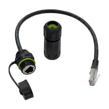
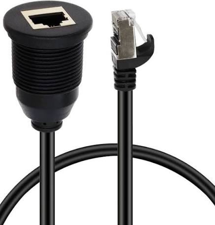
A cat6 rj45 panel mount cable takes an Ethernet port off the switch and puts it on the outside of the box, held by two screws instead of a friction latch. 24 AWG stranded UTP, 550 MHz, 50 micro-inch gold contacts, 3 ft as standard. Cut-out, pitch and length built to your drawing.
Overview
This cat6 rj45 panel mount cable takes an Ethernet port off the switch and puts it on the outside of an enclosure. The male end plugs into the host port on the switch or router; the female end is clamped to the panel with two M3 screws on a 27 mm pitch, so a tug on the patch lead cannot pull the connection out of the jack. It is wired straight-through to T568B, which is what an extension needs. Cat6 UTP at 24 AWG stranded carries Gigabit and 2.5G / 5G BASE-T inside the 100 m channel budget, and 50 micro-inch gold on the contacts keeps contact resistance from drifting upward after repeated mating cycles. This is a panel feedthrough, not a substitute for a sealed bulkhead: the rating here is mechanical retention and a clean through-panel port, not ingress protection.
Key Specifications
| Connector A | RJ45 Male, 8P8C |
|---|---|
| Connector B | RJ45 Female, panel-mount with screw lock |
| Category | Cat6 UTP |
| Conductor | 24 AWG stranded bare copper |
| Frequency | 550 MHz |
| Contact plating | 50 micro-inch gold |
| Cable OD | 6.2 mm |
| Jacket | PVC |
| Length | 3 ft (0.91 m) |
| Wiring | T568B straight-through |
| Panel fixing | Two M3 screws on a 27 mm pitch |
| Operating temperature | -20 C to +60 C |
How much of the 100 m budget does this extension eat?
Very little, but it has to be counted in the right place. Under the commercial building telecommunications cabling model published as TIA-568, the 100 m figure is the whole channel, and it is split between a 90 m permanent link and a combined 10 m of patch cordage at the two ends. An extension like this one is cordage, not permanent link, so 3 ft comes out of the 10 m allowance and not out of the 90 m in the wall. That distinction matters once a machine has several of them.
| Channel element | Commonly quoted allowance | Where this cable sits | What to watch |
|---|---|---|---|
| Permanent link | 90 m, solid conductor, terminated at both ends | Not this product – it is stranded, for patching | Stranded 24 AWG is not for in-wall runs |
| Patch cordage | 10 m combined across both ends | This cable, and the lead that plugs into it | Two extensions plus a 5 m lead is already most of the budget |
| Total channel | 100 m end to end | The sum, plus the device lead on each side | Add the device leads before you promise 100 m |
| Category mix | Backward compatible with Cat5e | Fine in a Cat5e channel at Cat5e performance | A Cat6 component in a Cat5e channel does not upgrade the channel |
Straight-through, and why the pinout still catches people out
An extension has to be pin 1 to pin 1, and it has to be T568B at both ends. Modern switch ports auto negotiate and most of them also auto crossover, so a crossover panel can sit undetected until a fixed-speed camera or an older PLC port is plugged in and the link will not come up. Do the crossing in a marked patch lead, never in the panel.
Panel cut-out and screw pitch: the two dimensions you cannot recover
Holes are permanent. A cut-out drilled 2 mm oversize leaves a flange with nothing to clamp against, and the usual repair – a backing plate bonded behind the panel – is more expensive than getting the drawing right. Take the aperture and the screw pitch off the connector flange drawing, not off a photograph or off a part that looks similar.
| Dimension | Value for this build | Why it bites | How to confirm |
|---|---|---|---|
| Panel cut-out | Match the connector flange on your drawing | Oversize leaves no land for the flange and no seal path | Flange drawing, plus a drilled test piece |
| Screw pitch | 27 mm between the two M3 fixings | The most common single reason a panel has to be remade | Measure center to center on the flange |
| Panel thickness | Confirm at order | Too thick and the screws will not pick up; too thin and the flange rocks | Measure at the mounting point, including any paint build |
| Rear clearance | Confirm at order | The mating plug plus its boot needs depth behind the panel | Depth gauge behind the panel, with the boot fitted |
| Bend radius | Keep well above the cable OD of 6.2 mm | A tight fold at the flange is where stranded pairs break | Leave a service loop behind the panel |
UTP in a panel: where the noise actually gets in
Unshielded does not mean unprotected, it means the protection comes from geometry and from routing. Twisted pair rejects noise because both conductors of a pair see the same interference and the receiver subtracts it; untwisting too much at the jack, running alongside a motor lead, or bonding the shell to a second ground all break that balance and show up as retransmissions rather than as a clean failure. Separate data from drive leads and tie lightly.
Where a Cat6 RJ45 panel mount cable earns its keep
- Control cabinets and PLC enclosures that need a service port on the door rather than inside
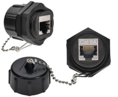
- Server racks and network cabinets where a patch point belongs on the panel, next to IP67 RJ45 Panel Coupler
- Wall plates and equipment housings that need a through-panel Ethernet extension, and where a IP67 Keystone Panel Frame would take a keystone module instead
- Kiosks and self-service terminals with an external laptop port, alongside our Control Cabinet Service Interface
- Outdoor and deck-mounted gear where the sealed option is the IP68 Deck Feedthrough Cable
- Single-pair field devices fed from a panel, see the SPE Bulkhead Panel Connector
- Machine builds that also need a shielded Ethernet drop, see Custom Shielded Ethernet Data Cable
- Installations that will later need a sealed patch lead, see Cat6 S/FTP IP67 Waterproof RJ45 Patch Cord
Failure modes we see on panel Ethernet runs
Three repeat. A cut-out drilled from a guess leaves the flange floating, so the jack rotates on every insertion and the screws pull through thin sheet. A cable dressed tight against the panel with no service loop puts the whole load on the strain relief until a stranded conductor breaks. And over-tightening deforms the plastic body – snug is enough.
How to specify your build
- Cut-out and screw pitch – off your panel drawing or the existing hardware.
- Panel thickness at the mounting point and what the panel is made of.
- Length – 3 ft is standard; longer runs on request.
- Wiring – T568B straight-through as standard, say if you need T568A.
- Jacket – PVC as standard; ask about LSZH where the run is in a plenum or a vehicle.
- Shielding – this is UTP; ask for the shielded build if the run sits next to drives.
- Quantity and whether this is a prototype or a production order.
Workmanship and testing
Build standard for Cat6 RJ45 Panel-Mount builds is IPC/WHMA-A-620 Class 3 under ISO 9001, with terminations from 32 to 12 AWG. continuity and pinout are checked on every Cat6 unit before packing, and seal checking is quoted whenever an ingress rating is on the drawing.
Every production run can ship with RoHS and REACH declarations and the electrical report agreed at quotation; see certifications and material declarations. UL styles and other named approvals are built to drawing: we source to the style you specify and document it, rather than asserting a listing we do not hold. Termination, molding and verification happen in-house see our assembly lines in Longgang so the process that made your sample is the process that runs the order. More background: engineering support and design for manufacture review. Tooling is quoted separately, cut in-house rather than brokered out, and owned by you.
Custom builds and ordering
On Cat6 RJ45 Panel-Mount builds, prototype lots run from 1 to 50 pcs and leave in 3 working days; production runs of 500 pcs and up ship 14 working days after approval. Tooling not already held adds around 10 working days. Cat6 OEM and ODM shipments carry your part number and labeling, and material certificates and first-article reports can be supplied.
Related panel and Ethernet hardware
- IP67 RJ45 Panel Coupler, Cat6A Shielded Bulkhead Feedthrough
- IP67 Keystone Panel Frame for Field-Replaceable Modules
- Control Cabinet Service Interface with RJ45 and USB-C
- SPE Bulkhead Panel Connector for 10BASE-T1L
- Cat5e UTP Patch Cord
Full ranges: panel mount cable, Ethernet patch cords and signal and data cables.
Frequently Asked Questions
Is a Cat6 extension in a Cat5e channel a waste?
Not a waste, but it does not upgrade anything. The channel performs to its weakest component, so the link negotiates at Cat5e rates. It is worth it when the panel hardware is being standardised ahead of a switch upgrade.
Can I mount it on a painted panel?
You can, but scrape the mounting land back to bare metal if the flange is expected to make electrical contact. On a purely mechanical UTP mount it matters far less than on a shielded bulkhead.
Do I need a crossover for a camera or a PLC?
No. Keep every panel extension straight-through and let the ports negotiate. A crossover belongs in a clearly marked patch lead, if it belongs anywhere at all.
| Connector A | RJ45 Male, 8P8C |
|---|---|
| Connector B | RJ45 Female, panel-mount with screw lock |
| Category | Cat6 UTP |
| Conductor | 24 AWG stranded bare copper |
| Frequency | 550 MHz |
| Contact plating | 50 micro-inch gold |
| Cable OD | 6.2 mm |
| Jacket | PVC |
| Length | 3 ft (0.91 m) |
| Wiring | T568B straight-through |
| Panel fixing | Two M3 screws on a 27 mm pitch |
| Operating temperature | -20 C to +60 C |