NMEA 2000 Backbone Design: Cable Grade, Length, Termination and Power Budget

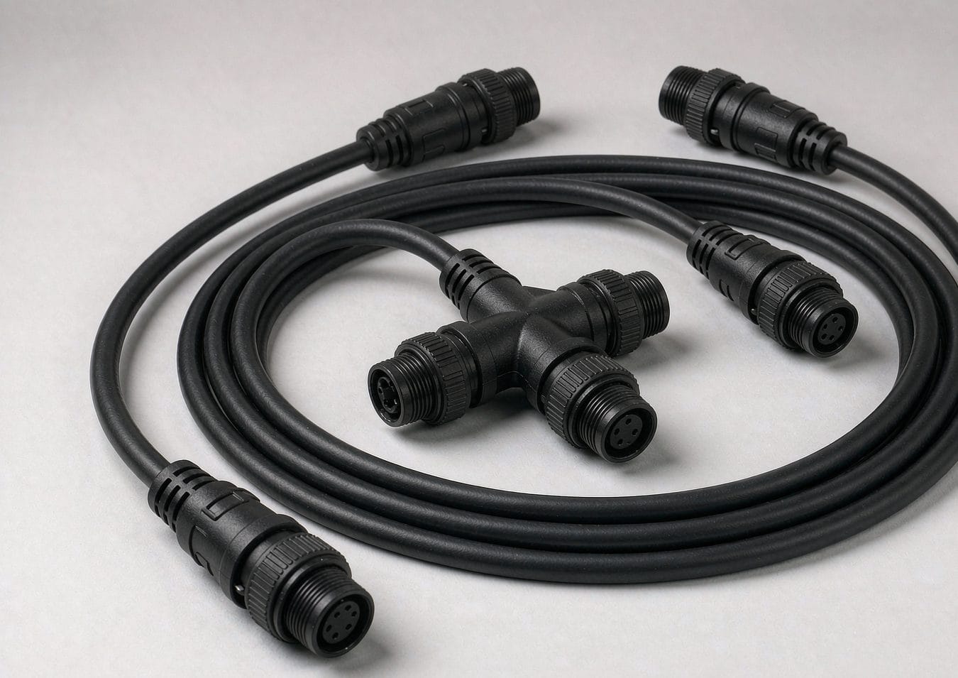
An NMEA 2000 backbone is the trunk every device on the boat hangs off, and it is the one part of the network you build once and then live with for a decade. This guide covers how to size it, how far it can run, how it has to be terminated and how much power it can carry, so the assembly you order matches the network you are actually installing.
What the backbone decides
The NMEA 2000 backbone is the part you only build once and then live with for a decade. Every device hangs off it through a tee, every terminator sits at one of its two ends, and every volt that reaches a chartplotter or an autopilot computer has to travel its length first. Get the backbone right and the network is boring, which is exactly what you want. Get it wrong and you spend seasons chasing intermittent dropouts that never reproduce on the bench.
This guide covers the backbone side of an NMEA 2000 network: cable grades, length limits, termination, power budget and where the supply goes in. The device-side rules — the 6 m drop limit, the 78 m cumulative drop budget and how to read a LEN number — are covered in our NMEA 2000 drop cable selection guide, so we only touch them here where they constrain the trunk.
Backbone and drop: the two-part topology
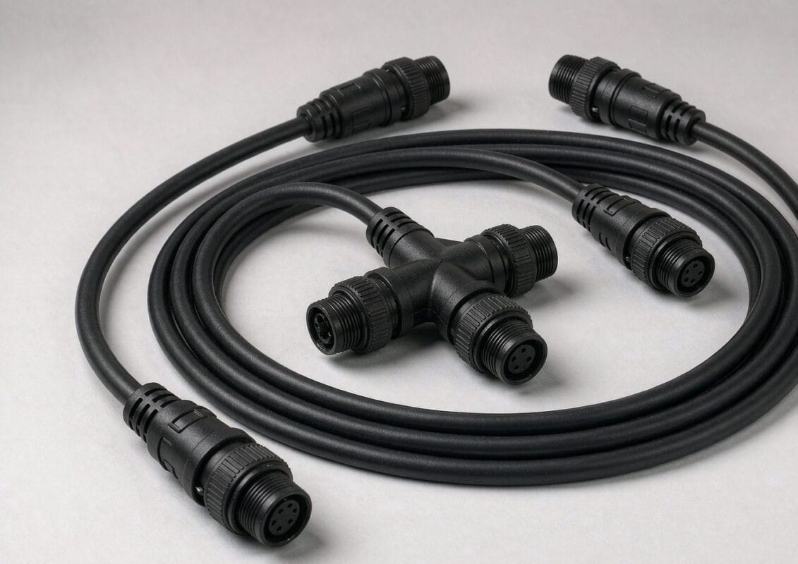
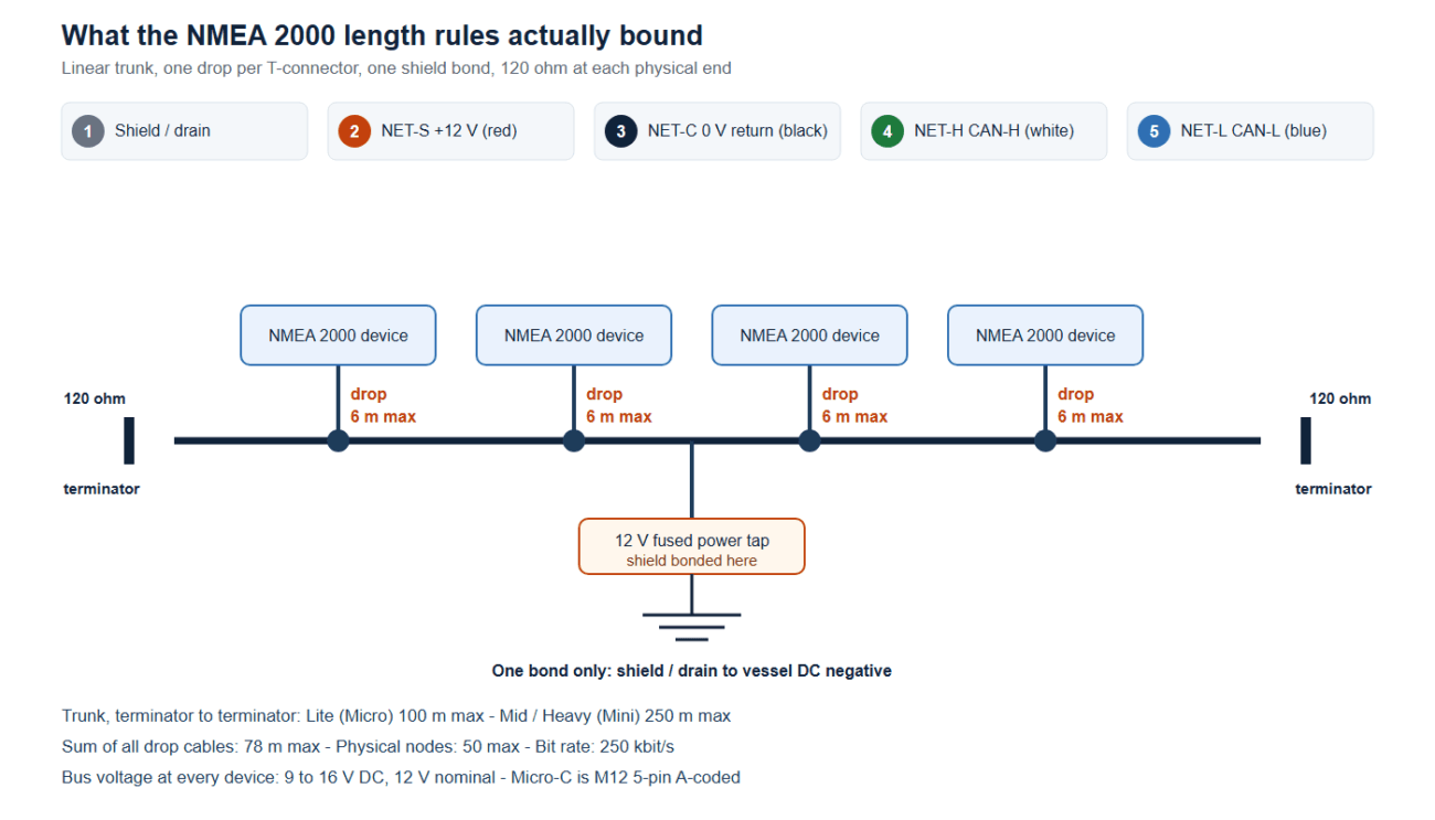
NMEA 2000 (IEC 61162-3) is a linear bus, not a star. The backbone is the trunk that runs the length of the boat; devices connect to it through T-pieces, and each device reaches its tee through a drop cable. The standard fixes two separate length numbers, and people mix them up constantly:
- Backbone length is measured from one terminator to the other, along the trunk, and it depends on the cable grade.
- Drop length is measured from the tee to the device. It is 6 m maximum per device, whatever cable grade you use, and the sum of all drops on the network cannot exceed 78 m.
The reason the two limits behave differently is simple enough: the drop limit is set by CAN bus timing, so it does not move when you buy better cable. The backbone limit is set mostly by voltage drop and signal degradation over distance, so it moves a long way with conductor size.
NMEA 2000 backbone cable grades: Lite, Mid and Heavy
NMEA 2000 adopts the DeviceNet cabling standard, which defines three grades. Most confusion in the field comes from the fact that the same grade has two names, one from each world.
| Grade | Also called | Data / power conductor | Resistance | Current | Max backbone |
|---|---|---|---|---|---|
| Lite | Micro / thin | 24 AWG data, 22 AWG power | 0.057 Ω/m | 3 A (Micro) | 100 m |
| Mid | Micro or Mini | 20 AWG data, 16 AWG power | 0.015 Ω/m | 4 A (Micro) or 8 A (Mini) | 200–250 m |
| Heavy | Mini / thick | 18 AWG data, 15 AWG power | 0.012 Ω/m | 8 A (Mini) | 200–250 m |
The 100 m figure for Lite cable is consistent across the sources we checked. For the Mini classes you will see both 200 m and 250 m quoted depending on whose summary you read, so treat anything past 200 m as a design you should verify against the cable maker’s own datasheet rather than a number to design to. Lite cable uses Micro connectors only; Mid cable can be terminated either way, and the connector you pick is what sets the current rating; Heavy cable is Mini only.
Both families use the same 5-pin M12 A-coded interface defined in IEC 61076-2-101: shield and drain on pin 1, NET-S and NET-C power on pins 2 and 3, CAN-H and CAN-L on pins 4 and 5.
What is inside the cable: pairs, shield, drain and jacket
The grade table tells you how much copper is in the cable. It does not tell you how that copper is arranged, and on a boat the arrangement matters as much as the size. An NMEA 2000 cable carries two twisted pairs plus a drain inside one overall shield: power on pins 2 and 3, data on pins 4 and 5, shield and drain on pin 1. The data pair is twisted because CAN is differential, and the twist is what makes the pair reject the noise a bilge pump or a windlass puts on the supply.
Shield construction is the first thing to specify. Depending on the grade and the maker, the overall shield is a foil, a braid, or both, and the difference shows up where the run has to survive handling: foil is lighter and cheaper, a braid takes flexing and gives the drain a low-impedance path to the bond point. We build to the construction you name on the drawing rather than substituting an equivalent, because a backbone that measures correctly on the bench can still be the wrong cable for a run that gets dragged through a bulkhead during installation.
Conductor plating and jacket come next, and both are marine decisions rather than electrical ones. Salt air finds untinned copper quickly, so the conductors on a boat backbone should be tinned. For the jacket, PVC is rarely the right answer on deck: a halogen-free low-smoke jacket is the common choice for runs inside a vessel, and PUR or TPU is the better answer where the cable is handled, coiled, flexed, or expected to stay flexible in the cold, since PVC stiffens at low temperature and a stiff cable pulls on every seal it passes through.
Bend radius, pull-out and strain relief at the tee
Most backbone failures that come back from the field are mechanical, and nearly all of them trace back to numbers nobody wrote down. Three belong on your drawing:
- Bend radius — quoted as a multiple of the cable outside diameter, and the multiplier depends entirely on what the cable does in service. A static run inside a conduit and a run that flexes with a mast or a hinged console do not get the same number.
- Pull-out force — the force the connector or the molded boot withstands before the cable moves in the body. This is a retention specification and it belongs on the drawing, not in a conversation.
- Support interval — how often the run is clipped. A long vertical drop that is only supported at the ends puts its whole weight on the top termination.
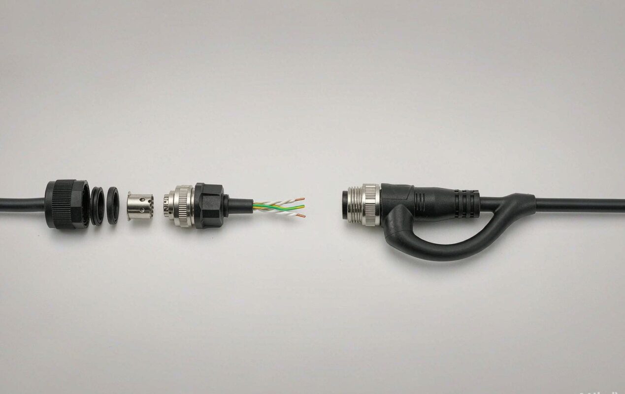
A molded strain relief is what spreads the bend at the transition from cable to connector instead of concentrating it at the crimp, and on a vibrating hull it is the difference between a termination that lasts a season and one that lasts a decade. The tee itself is the other mechanical weak point: it is a rigid body hanging in a flexible line, and it needs support on both sides so the backbone is not levering on the connector shells.
Sealing class at the tees and penetrations
Every backbone has at least two places where the IP class is decided, and neither is the connector datasheet. The first is the tee: it sits wherever you put it, which on a real boat is often a locker, a bilge edge or the base of a mast. A mated Micro-C connection is commonly specified IP67, and IP68 with a protective cap fitted, but those numbers assume a clean, correctly seated pair — the number that actually governs the tee is the one you write into the drawing for that location.
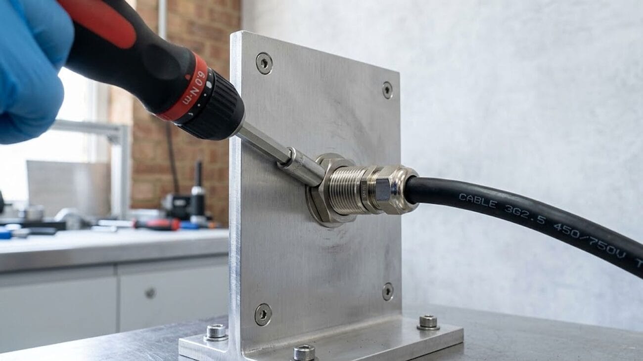
The second is the penetration. Where the run passes through a deck, a bulkhead or a coachroof, it stops being a cable and becomes a hole in a wall, and that is what our NMEA 2000 bulkhead connector is built for: sealed on both faces, with the cap class defined separately from the mated class. Runs that finish on deck usually end in an IP68 deck feedthrough rather than relying on the tee.
Two things the IP code does not cover are the ones that kill deck hardware: ultraviolet exposure and galvanic corrosion. In a salt environment, tell us what the panel is made of so the hardware is matched to it and you do not build a battery out of two dissimilar metals in seawater. Where the assembly is going on a mast or a deck edge, the weathering reference to qualify against is salt mist testing to IEC 60068-2-11.
Choosing a grade from the load, not the length
Length is the easy constraint. Voltage drop is the one that actually bites, because NMEA 2000 devices are bus powered: they take their operating current off the backbone. The standard expects every device to see between 9 V and 16 V at its tee, and a common field rule of thumb is that total drop across the network should stay under about 1.5 V.
Work it backwards on your own NMEA 2000 backbone. Add up the load in LEN — one LEN is 50 mA — and convert to amps. Then multiply by the one-way resistance of the run you are planning at the grade you intend to buy. On a Lite backbone at 0.057 Ω/m, a 20 m run to the far end is about 1.1 Ω out and the same back through the return conductor, so at 2 A you have already spent roughly 4.5 V of your budget. That same run in Mid cable costs about a quarter as much drop. This is why installers who started with Lite cable on a 12 m boat end up adding a second power tee halfway along a 25 m one.
The practical rule: Lite is fine for a small boat with a short, lightly loaded trunk. Move to Mid as soon as the run gets long, the device count climbs, or you are feeding large displays and an autopilot computer. A widely used guideline puts about 51 LEN (roughly 2.55 A) as the sensible ceiling for a backbone fed from a single insertion point; past that, split the trunk and feed each half from its own center, or add a second supply point.
Where the power goes in, and where the shield goes to ground
Two rules cover most of the power problems we see in the field. First, insert power at roughly the middle of the backbone so the voltage sags symmetrically toward both ends rather than collapsing at one extremity. Second, use one supply per bus. Two separate 12 V sources on the same backbone give current two return paths, and the resulting ground loop shows up as noise, dropped devices and, occasionally, cooked transceivers.
The shield has the same “one point only” rule for the same reason: bond the drain at the power insertion point and nowhere else. Grounding the shield at both ends turns it into a second return conductor.
NMEA 2000 backbone termination: two, exactly two
A CAN bus needs its characteristic impedance at each end or the signal reflects off the open ends. That means one 120 Ω terminator at each end of the backbone, and no others anywhere on the network. Because the two resistors are in parallel, a correctly terminated network measures about 60 Ω across CAN-H and CAN-L with the power off. That measurement is the single most useful diagnostic on the whole bus:
| Measured | What it means |
|---|---|
| ~60 Ω | Both terminators present, network healthy |
| ~120 Ω | One terminator missing or disconnected |
| ~40 Ω | A third terminator somewhere on the bus |
| Very low | Short between the data lines |
| Open | Break in the backbone or a conductor not terminated |
Devices with a built-in terminator are a known nuisance here, and it is worth checking for one before you assume a cable fault. Inline terminators exist for the awkward case where the trunk has to run up a mast and the physical end is not somewhere you can fit a plug.
How many devices, and what that does to the plan
On a finished NMEA 2000 backbone, the standard allows 50 physical connections and 252 addresses on a segment. In practice, power and length limit you well before the node count does. A typical cruising sailboat lands in the 30–45 LEN range with six to ten drops; a heavily instrumented powerboat with radar, multiple displays and an autopilot can double that. Either way, the design sequence is the same: list devices and LEN, sketch the route so no drop exceeds 6 m, pick the grade from the load, set the power point near the middle, then fit the terminators.
Where NMEA 2000 meets J1939 and OBD-II
NMEA 2000 did not invent its own message layer. It borrows it: the protocol is built on the SAE J1939 high-level protocol that commercial vehicles have used for decades, running on the same CAN physical layer at 250 kbps. The consequence is practical rather than academic — NMEA 2000 devices and J1939 devices can be made to coexist on one physical network, which is why you will see engine data from a marine diesel appear on a chartplotter without a gateway in between.
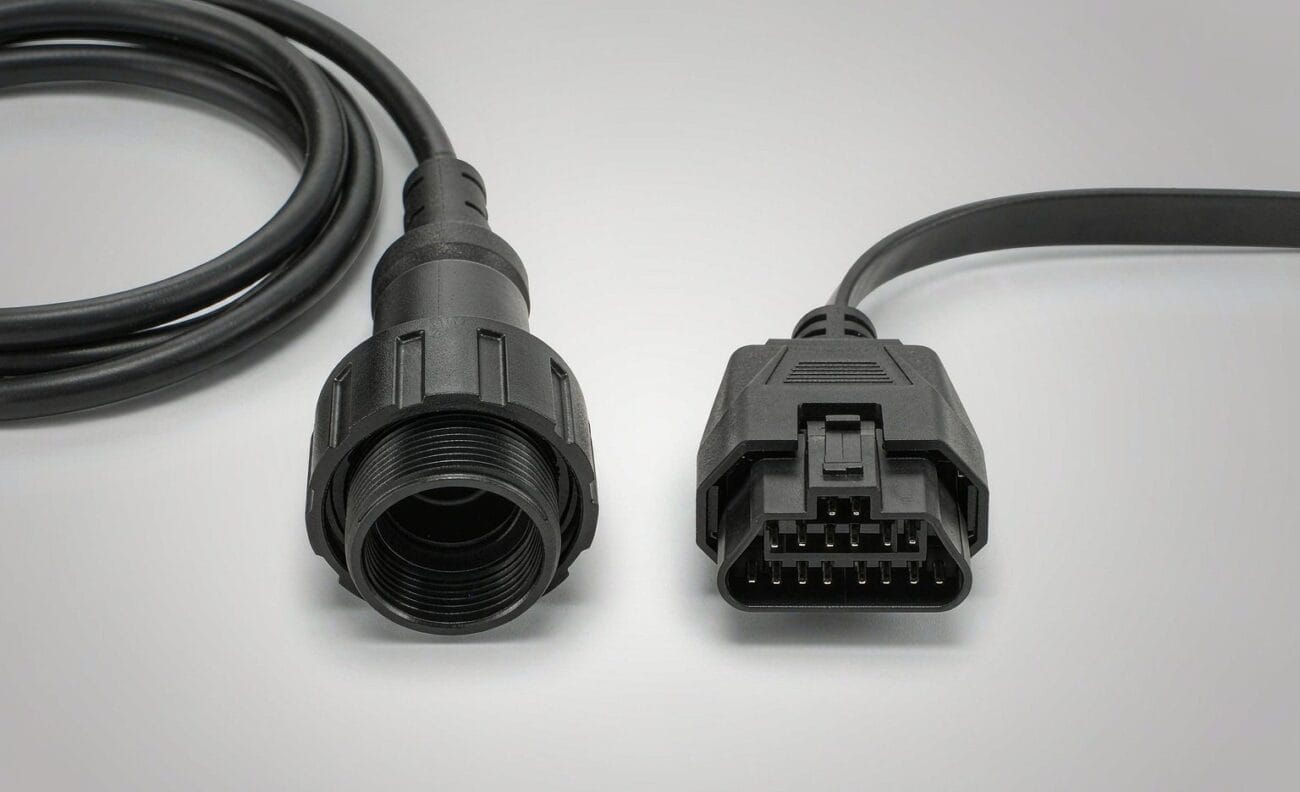
The family resemblance stops at the connector and the purpose. OBD-II is the light-duty diagnostic standard: a mandated 16-pin SAE J1962 connector, a request-response model where a tool asks and the vehicle answers, and roughly a hundred emissions-focused parameters. J1939 is the heavy-duty counterpart: a 9-pin Deutsch connector is the common arrangement, devices broadcast continuously rather than waiting to be asked, and the message set runs to thousands of parameter groups identified by PGN and SPN. One is a compliance interface for cars, the other is the working network inside a truck, a bus or a combine.
For cable assembly work the split matters because the environments do. A J1939 harness lives with vibration, temperature extremes, moisture and continuous bus traffic, so shielding, connector retention and jacket choice carry more weight than they do on a passenger-car diagnostic lead. That is the same engineering we apply on the automotive side — see our automotive cable and wire harness range, the M12 CAN bus cable and the J560 trailer ABS harness — and it is why a marine backbone and a truck harness often end up as the same construction with a different connector family on the ends.
What to put on the drawing before you order a backbone
A custom backbone assembly is only as good as the information behind it. The list that saves the most rework is short:
- Cable grade (Lite, Mid or Heavy) and the connector family at each end — Micro or Mini, and male or female
- Exact lengths between tees, not an overall run length, with the tee positions marked
- Where power enters, and whether you want a fused power tee supplied with the assembly
- Any bulkhead or deck penetration along the route, including panel thickness and the sealing class you need — see our NMEA 2000 bulkhead connector for what has to survive at that point
- Jacket and shield requirements: oil and fuel exposure in the engine room, UV exposure on deck, and whether the run passes through a bilge
- Whether you need mating NMEA 2000 drop cables or 5-pin T-splitters built in the same batch
Anything that depends on your installation rather than on our build — total LEN on the finished bus, voltage at the far tee, the 60 Ω check — stays on your commissioning sheet. We build and test the assembly to the drawing you sign off.
How we build and verify a custom backbone
Assemblies are built to your drawing or sample: cut to the lengths you specify, terminated with the connector family you choose, overmolded or field-fit at the penetrations, and 100% continuity and pinout tested before packing. Sealed sections are screened for leaks, and marine runs are built with tinned copper and a jacket chosen for the exposure you describe — the same decisions we cover for IP-rated waterproof cable assemblies. For the wider marine and outdoor picture, including salt-spray screening and acceptance criteria, see our marine and outdoor page.
One thing we will not do is guess at your network. If the drawing does not state a grade, a length or a pinout, we ask; a backbone that measures 60 Ω on the bench can still be wrong for the boat if two of those were assumed.
The verification list that ships with an assembly is short and specific:
- Continuity and pinout, 100% — every conductor, every pin, against your drawing, on every unit rather than on a sample
- Insulation resistance and dielectric withstand — at the test voltage stated on your drawing, so the number on the report is the number you designed to
- Air-leak screening, 100% — on the sealed sections and penetrations before packing, not on a sampling plan
- Retention — pull-out force at the termination and at the molded boot, to the value you specified
- Salt mist exposure — where the run is qualified to IEC 60068-2-11, to the duration and acceptance criterion you set, because hours alone mean nothing without one
Anything that depends on the finished installation — total LEN, the voltage at the far tee, the 60 Ω check — stays on your commissioning sheet. We hand you an assembly that matches the drawing and the report that proves it.
Samples, tooling and minimum order quantities
A backbone is usually worth prototyping before it is worth producing, because the first article is where tee positions turn out to be 200 mm off and a penetration turns out to be on the wrong side of a frame. Prototype quantities run from a single assembly up to about fifty, built from the drawing and continuity tested against the pinout you supplied. Production runs start at 500 pieces per part number.
Molded parts are the reason to plan ahead. Strain reliefs, boots and overmolded tee bodies need tooling, and we cut that tooling in house — more than 3,000 tooling sets built since 2012, with over 100 active molds maintained on site. The tooling for your program is your property, which is what makes a repeat run two seasons later pick up where the last one left off instead of paying to reopen a tooling conversation.
Lead time is quoted with the sample rather than quoted blind, because on a custom backbone it is set by the parts that are not the cable: connector availability, whether new tooling is needed, and how long the first article takes to approve. Send the drawing and we will put a number and a sample date on the quote.
Frequently asked questions
How long can an NMEA 2000 backbone be?
100 m for Lite (Micro) cable, which is the figure every source agrees on. For Mid and Heavy (Mini) cable you will find both 200 m and 250 m quoted; design to 200 m and confirm against the cable datasheet before going further.
Can I extend a drop cable instead of extending the backbone?
No. The 6 m per-device drop limit and the 78 m cumulative drop limit do not change with cable grade, because they are set by CAN timing rather than by voltage drop. Extend the trunk and keep the drop short.
Why does my network measure 40 ohms instead of 60?
There is a third 120 Ω terminator on the bus. Check for a device with a built-in terminator, or a terminator left fitted at what used to be the end of the network.
Do I need two power supplies on a long backbone?
Not two supplies on one bus. If the load exceeds what a single center-fed insertion can carry at 9 V or better at the far tee, split the network into two segments with their own supply, rather than tying two sources to the same trunk.
Is Mid cable worth the extra cost on a small boat?
Usually not. On a short, lightly loaded trunk Lite cable stays comfortably inside the voltage budget. It becomes worth it as soon as the run gets long or the device list includes radar, large displays or an autopilot computer.
Can you build the backbone and the drops in one batch?
Yes, and it is usually the cheaper route, because the termination setup and the test fixtures are the same for both. Send the tee positions and drop lengths together.
What is the minimum order for a custom backbone?
Prototype quantities start at one assembly and run to about fifty. Production starts at 500 pieces per part number. If the design needs new molded parts, the tooling is built in house and belongs to your program.
What tests come with the assembly?
Every unit gets continuity and pinout testing, sealed sections get 100% air-leak screening, and insulation resistance, dielectric withstand and retention are tested to the values on your drawing. Salt mist exposure is run when you specify it, to the duration and acceptance criterion you set.
Can you match an existing backbone or sample?
Yes. Send the sample or the drawing with tee positions, lengths, connector family and pinout, and we will build to it and return a first article for approval before production.
Can you supply NMEA 2000 approved cable?
We build to the cable and connector specification you name on the drawing, including DeviceNet-grade constructions. Certification of the finished network is a matter for the device makers and the installer, and we do not claim an approval we do not hold.
Send us the backbone drawing
Send the tee layout, lengths, connector family and the sealing class at each penetration, and we will quote the assembly, the terminations and the moulded parts together, with a sample before production if the run is a long one.