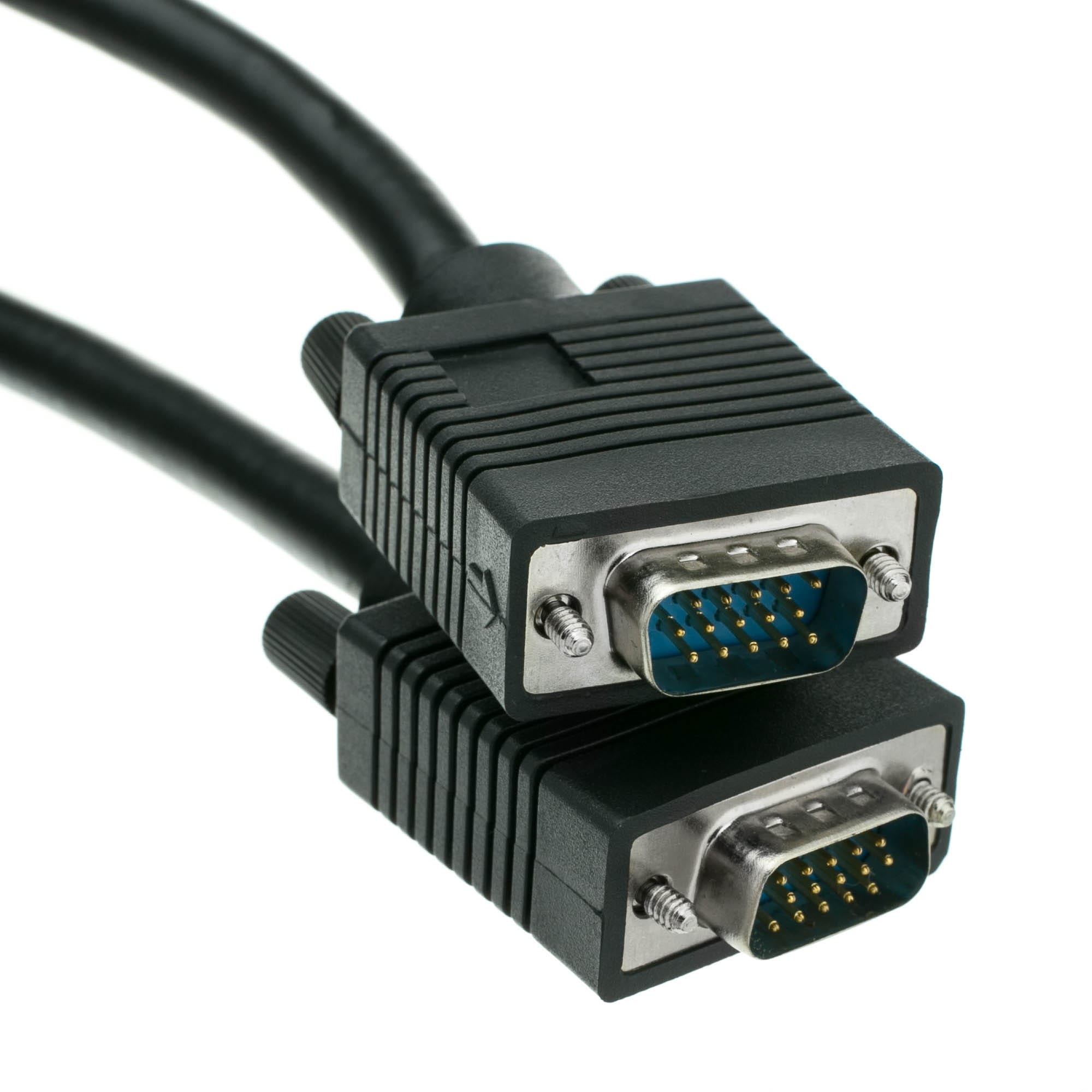
VGA Screw Lock Cable, HD15 for Industrial Monitors and CNC Panels
A VGA screw lock cable keeps an HD15 plug seated on a machine that vibrates, and carries three analog color channels far enough to stay readable. Coax cores, low capacitance, two jackscrews into the panel threads, molded to your length.
Last updated: 13 September 2026
Overview
A VGA screw lock cable is a part people assume died with the CRT, and then discover they still need in volume. The reason is simple: an enormous installed base of industrial monitors, CNC controllers, KVM trays and inspection stations still runs an HD15 port, and replacing any of it means re-validating a machine rather than swapping a lead. VGA is analog, which means the cable is part of the signal path in a way it never is for a digital link – construction decides whether the picture is readable, not just whether it arrives. We build these with three properly sized coax cores for the color channels, an overall braid, and two jackscrews that clamp the shell into the panel threads.
Why the HD15 port outlived the CRT
VGA arrived with analog monitors and should logically have gone out with them. What kept it alive on plant equipment is that an industrial panel PC is not a consumer monitor: it is specified, mounted, wired and validated as part of a machine, and the port on the back of it is documented in the machine manual. Digital video needs a handshake, a driver and a working firmware revision; VGA needs three color channels and two sync lines. The result is that a factory running fifteen-year-old machining centers buys more HD15 leads than it buys HDMI ones.
Analog degrades; digital drops out
A digital link either arrives or it does not – you get sparkles, then a black screen. VGA is three analog color channels plus horizontal and vertical sync, and every meter of cable rounds off the edges, adds capacitance and picks up noise. The symptom is never a clean failure. It is a soft picture, ghosting on vertical edges, color that will not converge, a visible smear after a bright edge, or a monitor that locks only when somebody holds the plug. Because the degradation is gradual, it gets blamed on the graphics card, the monitor, or the operator, and the cable is the last thing anyone replaces – usually correctly, because the cable is usually the cause.
HD15 pin assignment
The HD15 is a high-density D-Sub: fifteen contacts in three rows in a DE-size shell. This is the general industry arrangement for the analog interface; we wire to the pinout on your drawing, not to a chart, and some equipment deviates.
| Pin | Signal | Pin | Signal |
|---|---|---|---|
| 1 | Red video | 9 | Key / +5 V from the monitor (often no connect) |
| 2 | Green video | 10 | Sync return (ground) |
| 3 | Blue video | 11 | ID0 / monitor identifier |
| 4 | ID2 / reserved | 12 | ID1 / serial data |
| 5 | Ground | 13 | Horizontal sync |
| 6 | Red return | 14 | Vertical sync |
| 7 | Green return | 15 | Serial clock / ID3 |
| 8 | Blue return | Shell | Overall screen |
Two of those are worth understanding. Pins 6, 7 and 8 are the individual returns for the three color channels, not spare grounds – each color core is a coax with its own return, and tying them all to pin 5 at the plug is a common way to wreck the picture. Pins 11, 12, 4 and 15 are the display identification channel used by the monitor to describe itself to the source; if your equipment relies on it, say so, because a cable that omits it will not be detected.
What the cable itself has to do
Each of the red, green and blue channels rides on its own coax-style core with its own return. The capacitance per unit length of that core, working against the source impedance, behaves as a low-pass filter: the longer the run and the higher the capacitance, the more the high frequencies roll off – and the high frequencies are what put a crisp edge on text. Building the three channels on properly sized coax keeps that roll-off low enough that a run across a machine is still readable. Thin signal wire in a cheap lead degrades well before that distance.
Why the screws survive a machine tool
An HD15 plug without retention depends on the grip of its contacts and on the weight of the cable hanging behind it. Put that on a machining center, a press, or a cabinet with a fan tray and the vibration does the rest: the plug frets in the socket, the picture flickers, and eventually a pin loses contact. The two jackscrews on a retained plug clamp the shell to the panel threads so the connector and the socket move as one piece, and the leverage of a stiff cable hanging off the back is carried by the shell rather than by fifteen contacts.
Key specifications
| Connector A | HD15 / DE-15 male with retained jackscrews |
|---|---|
| Connector B | HD15 male, female, or a panel-mount feed-through |
| Interface | VGA, 15-pin D-sub per the original IBM / VESA analog pinout |
| Retention | Two jackscrews clamping to the mating panel threads |
| Signal cores | Three coax-style color channels plus sync conductors |
| Shielding | Overall braid plus individual channel screening – confirm per build |
| Jacket | PVC as standard, PUR on request |
| Shell orientation | Straight or right-angle molded hood |
| Application | Industrial monitors, CNC panels, KVM trays, inspection stations |
| Length | Made to order |
Typical applications for this VGA screw lock cable
- Industrial panel PCs and operator stations on older production lines
- CNC controllers from the 1990s and early 2000s that will never be upgraded
- KVM trays and rack consoles in server and control rooms
- Inspection, measurement and test stations with legacy capture hardware
What to tell us
- Run length, and whether it passes near variable-speed drives or contactors.
- Male-to-male extension, or a male plug to a panel-mount feed-through.
- Straight or right-angle at either end, and the exit direction.
- Whether the display identification channel needs to be connected.
- Whether the machine is grounded the way the display expects.
- Ferrite suppression or jacket color requirements, and the quantity.
Workmanship and testing
ISO 9001 governs the line and IPC/WHMA-A-620 Class 3 governs the workmanship. Terminations cover 32 to 12 AWG. No unit is packed before continuity and pinout have been verified, and where an ingress rating is specified we can quote seal checking on the production batch.
Custom builds and ordering
Prototypes are quoted from 5 pcs and ship within 3 working days. Volume production starts at 500 pcs with a 14 working day lead time after approval, and about 10 working days more when a new tool is needed. Private labeling carries your part number, and material certificates with first-article reports are available on request.
Related video and screw-lock assemblies
- VGA HD15 Monitor Extension Cable
- VGA HD15 Video Cable 1.5 m
- VGA HD15 1 Male to 2 Female Y Splitter
- 13W3 to VGA (HD15) Mixed-Contact D-Sub Cable
- DVI Screw Lock Cable, DVI-D and DVI-I for legacy industrial PCs
- D-Sub Screw Lock Cable, DB9 DB15 DB25 Serial and I/O Cordset
The connector and its history are covered in the VGA connector reference. Full ranges: Screw-Lock Molded Cable • Audio Video Cable • Signal and Data Cables.
Frequently Asked Questions
How long can a VGA run be before the picture degrades?
It depends on the cable construction and the resolution, not on a number printed on the jacket. Coax cores with a low capacitance per meter hold up far longer than thin signal wire. Tell us the length and resolution and we will size the cores for it.
Do I need the display identification pins connected?
Only if your source relies on reading the monitor. Many industrial setups force the resolution instead, in which case those conductors are unused. Say which applies.
Can you build one end as a panel-mount feed-through?
Yes. A male plug to a panel receptacle is a common build for machine enclosures, and we can supply the mating hardware with it.
Why does my picture have a ghost image offset to the right?
That is a reflection from an impedance mismatch, and a long or poorly built cable is the usual cause.
What is the minimum order?
The smallest build we quote is 5 pcs, shipping 3 working days later. Production quantities start at 500 pcs and ship 14 working days from sample approval.
| Connector A | HD15 / DE-15 male with retained jackscrews |
|---|---|
| Connector B | HD15 male, female, or a panel-mount feed-through |
| Interface | VGA, 15-pin D-sub per the original IBM / VESA analogue pinout |
| Retention | Two jackscrews clamping to the mating panel threads |
| Signal cores | Three coax-style color channels plus sync conductors |
| Shielding | Overall braid plus individual channel screening – confirm per build |
| Jacket | PVC as standard, PUR on request |
| Shell orientation | Straight or right-angle molded hood |
| Application | Industrial monitors, CNC panels, KVM trays, inspection stations |
| Length | Made to order |
Related products
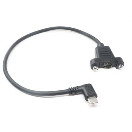
Right Angle Type C male USB Cable to Femal socket with screw-lock
Right‑Angle Screw‑Lock Type‑C Cable | Male to Female Extension Cord