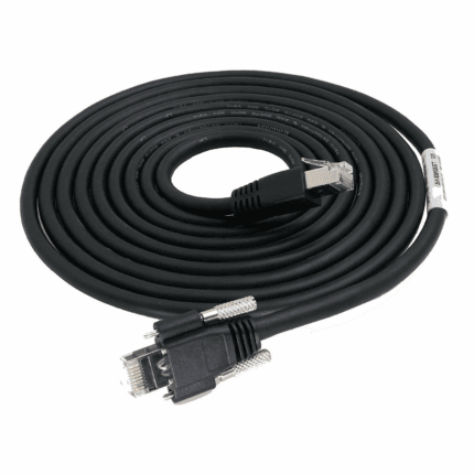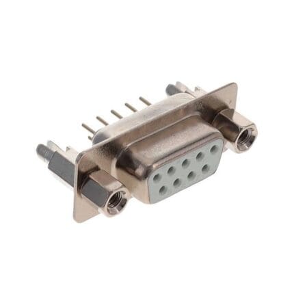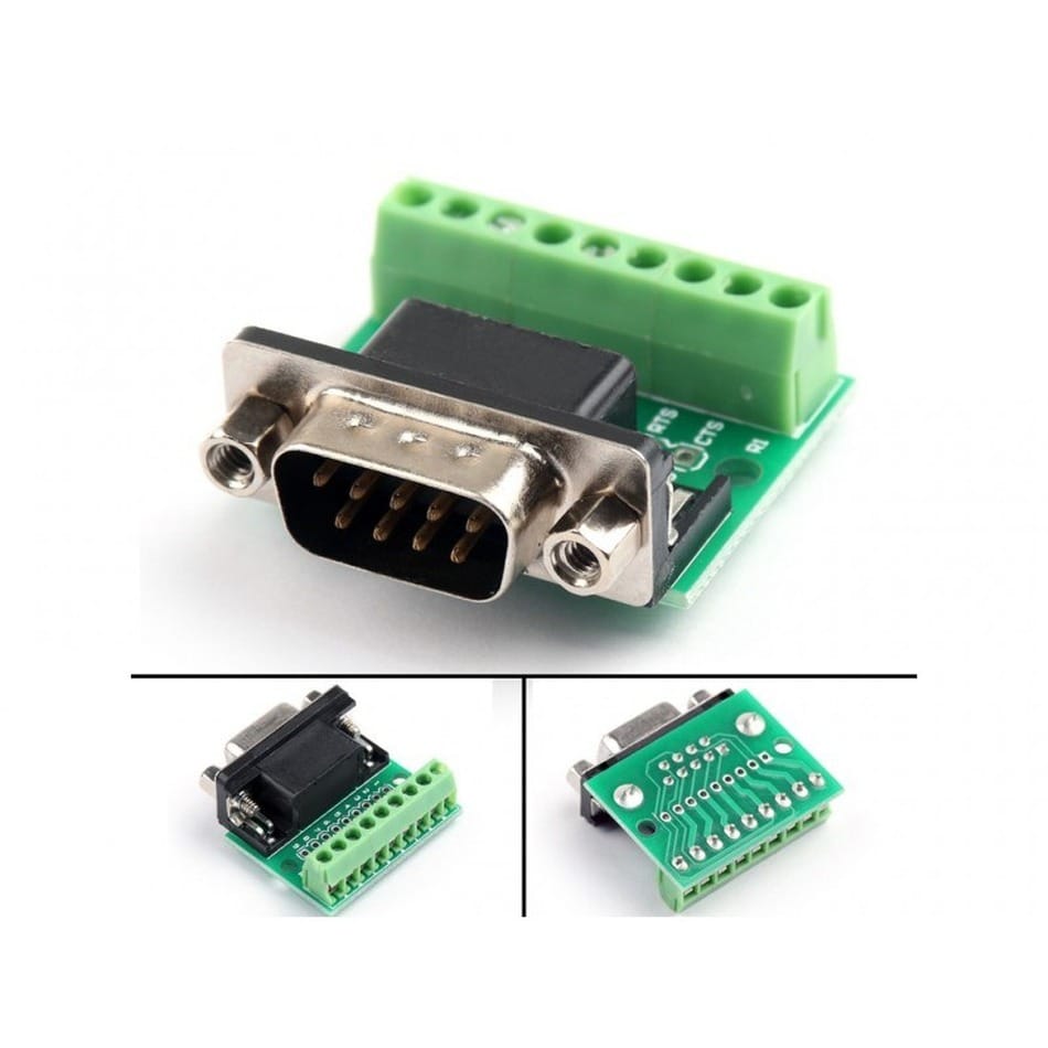
DB9 RS485 Screw Cable for Modbus RTU Multi-Drop Runs
A DB9 RS485 screw cable carries a Modbus RTU segment over one shielded twisted pair, with the shell clamped down so vibration cannot back the plug out of the device. Send us the pinout: DB9 serial assignments are not standardized between equipment vendors.
Overview
A DB9 RS485 screw cable is the physical layer under a Modbus RTU segment, and almost every “Modbus is unreliable” report we hear about turns out to be a wiring problem rather than a protocol problem. Three things decide whether a segment runs cleanly for a decade: the two conductors carrying the differential pair have to be a genuine twisted pair, the bus has to be one trunk rather than a star, and the ends have to be terminated and biased correctly. This cordset is built with one shielded twisted pair plus drain, in a screw-retained DE-9 shell so the plug cannot work loose out of a drive or an energy meter. The pinout comes from you.
What Modbus RTU asks of the physical layer
Modbus RTU itself is an application-layer protocol: it defines message framing and addressing, not the electrical signaling. On almost every installation it rides on the balanced differential interface described by TIA/EIA-485, a general industry definition of the electrical layer rather than anything specific to Modbus. That layer sends each symbol as the voltage difference between two conductors instead of as a level referenced to ground, so noise induced along the run lands on both conductors together and cancels at the receiver. It only holds if the two conductors stay close together, which is why twisted pair is not optional.
Two-wire or four-wire
Modbus RTU runs on both, and mixing them on one segment is a guaranteed fault.
| Two-wire (half duplex) | Four-wire (full duplex) | |
|---|---|---|
| Conductors | One twisted pair, usually labeled A / B or D+ / D- | Two twisted pairs – one transmit pair, one receive pair |
| Direction | Half duplex: master talks, then listens | Full duplex: transmit and receive run at once |
| Master to slave | One pair connects all devices | Master transmit pair lands on every slave receive pair |
| Slave to master | Same pair, slaves take turns | All slave transmit pairs land on the master receive pair |
| Typical use | Almost all new Modbus RTU segments | Legacy four-wire devices, some gateways and repeaters |
| Common mistake | A and B swapped at one node, which silences or garbles it | Wiring it as two-wire, or leaving the unused pair unterminated |
Note the naming, because it is the biggest source of confusion on site: some makers label the pair A / B, others call it D+ / D-, and a few reverse the sense of A and B. If one node on a segment is silent, swap its two conductors before you do anything else.
Termination and bias: two resistors decide whether the segment works
A bus is a transmission line. When an edge reaches an open end it reflects back along the pair and corrupts the next symbol, so each end of the trunk needs a terminating resistor whose value matches the characteristic impedance of the cable being used. Separately, when no device is driving the pair, bias resistors hold the line in a known state, otherwise the receivers interpret noise as data. Whether your segment needs either depends entirely on your equipment: many devices already have terminators fitted behind a jumper, and some masters provide the bias internally. Confirm both against the device documentation and the cable you are actually using instead of adopting a default.
Topology: one trunk, short spurs
RS-485 is defined as a bus, not a star. One trunk visits each node in turn with the shortest spur you can manage off it; a long branch is a stub that reflects. In practice that means daisy-chaining from device to device rather than running home runs back to a junction box. Send us the node count and the spacing between nodes and we will comment on the topology before you buy cable.
DB9 pin assignments are not standardized
This is the expensive mistake. The nine-pin shell is the connector, not the pinout. Which pins carry the differential pair, which carry the signal reference, and which carry a supply or a bias are decided by the equipment maker, and two devices in the same cabinet can disagree completely. The table below is a set of arrangements we are often asked to build – it is not a standard, and it does not tell you what your device does.
| Pin | Arrangement we often see | Alternative we often see | Why it varies |
|---|---|---|---|
| 1 | Not connected | Shield / drain | Some makers tie the screen to the shell only |
| 2 | Data B (inverting) | Not connected | Pair position is vendor-specific |
| 3 | Data A (non-inverting) | Data B | A and B are sometimes reversed |
| 4 | Not connected | Data A | Four-wire devices need a second pair |
| 5 | Signal reference (common) | Signal reference | The one pin most makers agree on |
| 6 – 9 | Supply, bias or unused | Second pair, supply or unused | Driven by what the device needs to power |
Order without stating the pinout and you receive a perfectly built cable that does not work. Send the pinout, the device model, or a photo of both ports.
Key specifications
| Connector A | DB9 / DE-9, straight or right-angle, male or female |
|---|---|
| Connector B | DB9 / DE-9 or open leads |
| Interface | RS-485 balanced differential pair (TIA/EIA-485 electrical layer) |
| Protocol | Modbus RTU and other multi-drop serial fieldbuses |
| Retention | Screw-retained shell, #4-40 UNC class hardware – confirm per build |
| Conductors | 1 shielded twisted pair plus drain, extra cores on request |
| Jacket | PVC or PUR |
| Termination | Resistor value and placement to be confirmed against the device – specify at order |
| Application | Modbus RTU segments, drives, meters, remote I/O, HVAC plant |
| Length | Made to order, segments planned as one trunk with short spurs |
Typical applications for this DB9 RS485 screw cable
- Modbus RTU segments linking a master PLC to drives, meters and remote I/O
- HVAC plant: air handlers, chillers, valve and damper controllers
- Retrofit segments replacing worn two-core cable that was never twisted
Ordering checklist
- The pinout – or the device model, or a photograph of both connector faces.
- Gender at each end, and straight or right-angle.
- Two-wire or four-wire, and the conductor labeling your devices use.
- Length, node count and spacing between nodes.
- Whether terminations are needed, at which end, and at what value.
- Jacket: PVC for cabinet runs, PUR where there is oil, coolant or washdown.
Workmanship and testing
For DB9 RS485 Screw builds the line runs to IPC/WHMA-A-620 Class 3 under ISO 9001, terminating 32 to 12 AWG. Every DB9 build gets a continuity and pinout check before it is boxed, and seal checking is quoted whenever an ingress rating is on the drawing.
Every production run can ship with RoHS and REACH declarations and the electrical report agreed at quotation; see certifications and material declarations. UL styles and other named approvals are built to drawing: we source to the style you specify and document it, rather than asserting a listing we do not hold. Production runs on the same lines described under our assembly lines in Longgang, where cutting, termination, molding and 100 percent electrical verification sit under one roof. Related reading: our build-to-print process. Tooling is quoted separately, cut in-house rather than brokered out, and owned by you.
Custom builds and ordering
DB9 RS485 Screw prototype lots start from 1 to 50 pcs and ship in 3 working days. Production requires 500 pcs and runs 14 working days after sample approval. Tooling not already held adds around 10 working days. Your part number and labeling go on OEM and ODM DB9 shipments, and material certificates and first-article reports are on offer.
Related serial and screw-lock assemblies
- D-Sub Screw Lock Cable, DB9 DB15 DB25 Serial and I/O Cordset
- DB9 to RJ45 Serial / Console Cable
- Screw Lock Console Cable, DB9 to RJ45 for rack management ports
- BMS Communication Harness for CAN and RS-485 battery rack links
- 10BASE-T1L Screw Lock Cable with sealed M8 or IEC 63171-6 couplings
- IP67 RJ45 Screw-Lock Bulkhead Cable for the panel entry
The electrical layer is described in the RS-485 reference. Full ranges: Screw-Lock Molded Cable • Signal and Data Cables • Panel Mount Cable.
Frequently Asked Questions
Can you supply a standard DB9 RS-485 pinout?
There is not one. The shell is standardized; the assignment is set by the equipment maker and differs between vendors. Send the pinout, the device model, or a photo of both ports.
Do I need terminating resistors?
Usually yes at each end of the trunk, with a value matched to the characteristic impedance of the cable you are using. Many devices already have one fitted behind a jumper – check before adding another.
Can I add cores for a supply feed?
Yes. One shielded twisted pair plus drain is the default; extra cores for a supply or a bias can be added.
What is the minimum order?
Evaluation units run from 1 to 50 pcs, turned around in 3 working days. Volume starts at 500 pcs and ships 14 working days after approval.
| Connector A | DB9 / DE-9, straight or right-angle, male or female |
|---|---|
| Connector B | DB9 / DE-9 or open leads |
| Interface | RS-485 balanced differential pair (TIA/EIA-485 electrical layer) |
| Protocol | Modbus RTU and other multi-drop serial fieldbuses |
| Retention | Screw-retained shell, #4-40 UNC class hardware – confirm per build |
| Conductors | 1 shielded twisted pair plus drain, extra cores on request |
| Jacket | PVC or PUR |
| Termination | Resistor value and placement to be confirmed against the device – specify at order |
| Application | Modbus RTU segments, drives, meters, remote I/O, HVAC plant |
| Length | Made to order, segments planned as one trunk with short spurs |