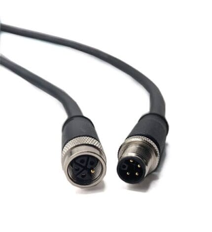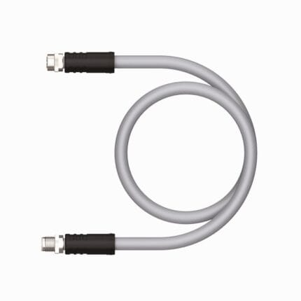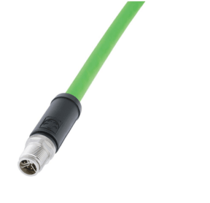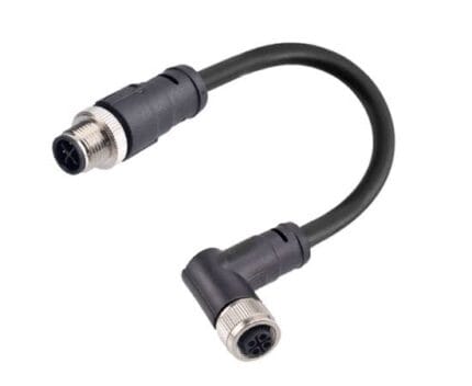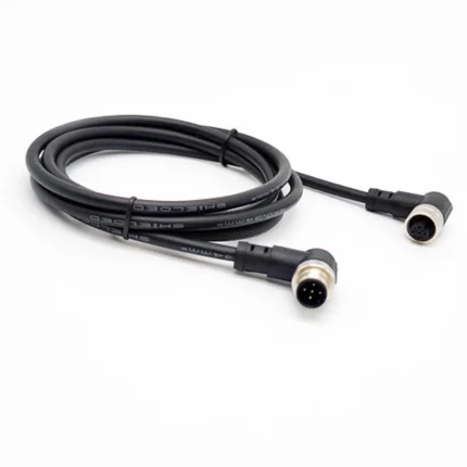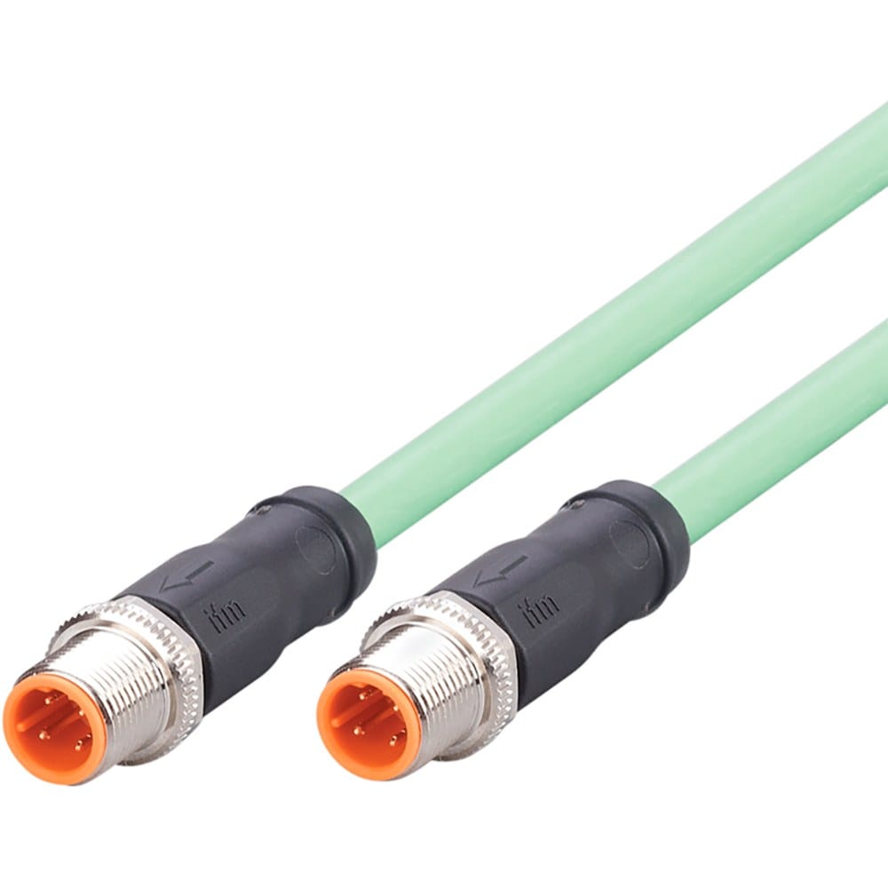
M12 IO-Link Cable, Master to Device Drop for 3 and 4 Wire Ports
An M12 IO-Link cable for master-to-device drops on 3-wire and 4-wire installations, built for port class A or port class B. Conductors sized to your drop length rather than picked from a default, so the device still sees a healthy supply at the far end.
Last updated: 13 September 2026
Overview
An M12 IO-Link cable looks like an ordinary sensor cordset, and in most cases that is exactly what it is. IO-Link is deliberately simple at the physical layer: one master port talks to one device over three or four conductors that carry the supply and the switched signal together. That is why the cable is unremarkable and the specification is not – the same pair carries 24 V and the communication signal, so conductor size, contact quality and drop length decide whether a device stays online.
Key Specifications
| Coding | A-code, sensor and actuator |
|---|---|
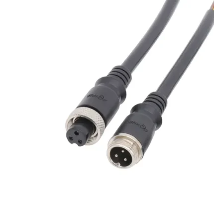
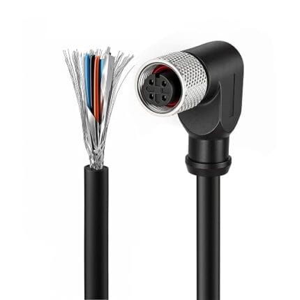
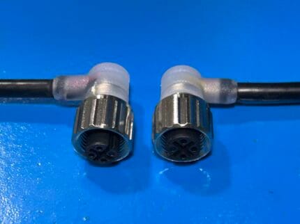
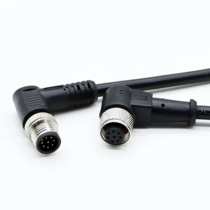
| Connector A | M12 A-coded, 3, 4 or 5 pins, straight or right-angle |
| Connector B | M12 A-coded, or open leads |
| Wiring | 3-wire or 4-wire, port class A or port class B |
| Supply | 24 V DC sensor supply – confirm per build |
| Conductor size | Sized to the drop length – state the run |
| Jacket | PUR for washdown and coolant, PVC for dry panels |
| Shielding | Unshielded as standard; shielded option for heavy EMC areas |
| Ingress rating | IP67 when mated – confirm per build |
The cable is ordinary. The drop is not.
IO-Link is a point-to-point link rather than a bus: one master port talks to one device over three or four conductors. Because the supply and the signal share conductors, anything that drops voltage at the far end shows up as a communication fault rather than as a power fault. Undersized cores let the device brown out and re-enumerate. A marginal crimp does the same intermittently, which is far harder to diagnose than a hard break. On a long drop the conductor choice matters more than the protocol does, and that is the number we ask for first.
Port class A and port class B pinout reference
The difference between the two port classes is whether the port offers a second supply pair for higher-power devices. On a class A port pins 2 and 5 are not used; on a class B port they carry the additional supply. Get this wrong and an actuator will not move even though the link associates correctly.
| Pin | Port class A | Port class B | Typical color | Note |
|---|---|---|---|---|
| 1 | L+ (24 V) | L+ (24 V) | Brown | Device and communication supply |
| 2 | Not connected | P24 – additional supply +24 V | White | Present on class B ports only |
| 3 | L- (0 V) | L- (0 V) | Blue | Return |
| 4 | C/Q – communication and switching | C/Q – communication and switching | Black | The signal contact; the one that decides link quality |
| 5 | Not connected | P0V – additional supply 0 V | Gray | Present on class B ports only |
We terminate to the pinout you send. Where a machine mixes class A and class B devices, tell us and we will suggest a jacket color or a printed legend so the two are not swapped during maintenance.
Where IO-Link sits in the M12 coding family
IO-Link runs on the general-purpose A-code, the same keyway as an ordinary sensor cordset. Everything else in the family is keyed for a different job – fieldbus, Ethernet, AC power, DC power or a hybrid. The map below is what each coding is for and how many positions it normally uses.
| Code | Positions | Carries | Typical use |
|---|---|---|---|
| A | 3 / 4 / 5 / 8 / 12 | DC sensor supply and signals, IO-Link | Proximity switches, photoelectric sensors, valve plugs |
| B | 5 | PROFIBUS-DP fieldbus | Legacy drives, remote I/O racks, weigh scales |
| C | 3 to 6 | AC power, dual keyway, extended earth | AC sensors, solenoid coils, legacy actuator blocks |
| D | 4 | 100 Mbit/s Ethernet over two pairs | PROFINET, EtherNet/IP, EtherCAT device drops |
| K | 4 + PE | Three-phase AC power | Motor feeds, power distribution blocks |
| L | 4 + PE | DC power | IO-Link power, AGV and drive supplies |
| M | 5 + PE | Three-phase motor plus brake pair | Servo and geared motors with holding brake |
| P | 4 + PE | Data pairs plus 24 V DC supply | Single-cable EtherCAT and remote I/O blocks |
| S | 3 + PE | Single-phase AC power | Field I/O blocks, cabinet heaters, pumps, fans |
| T | 4 | DC power, two circuits | Low-voltage DC distribution |
| X | 8 | Up to 10 Gbit/s Ethernet over four pairs | Machine vision, M12 to RJ45 10G links |
| Y | 6 + PE / 8 | Hybrid power plus Fast Ethernet | Valve islands, hybrid power and data drops |
A, B, C and D are set out in IEC 61076-2-101, X in IEC 61076-2-109 and the power codings in IEC 61076-2-111. Y is a de-facto hybrid arrangement rather than an IEC-defined code. These are the industry-standard descriptions of purpose; the current and voltage figures your assembly is built and verified to are the ones stated on your drawing.
Drop length, conductor size and what we check
| Drop condition | What we check | What changes in the build |
|---|---|---|
| Short drop in a cabinet or on a nearby manifold | Standard cordset is adequate | Default conductor size, unshielded |
| Medium run across a machine | Voltage at the device under load | Step up one conductor size |
| Long run to a remote device | Voltage drop and re-enumeration margin | Larger cores, or move the master closer |
| Run past drives or weld equipment | EMC environment | Shielded build with the braid bonded to the coupling nut |
IO-Link itself is covered by IEC 61131-9 as an industry standard, and the description here is the general one – your assembly is built and verified to the values on your drawing, not to a catalog number. Tell us the actual run and we size the conductors so the device still sees a healthy supply at the far end.
How we build these
- A-coded M12 heads in straight or right-angle form, male or female, molded in volume
- PVC for dry panels, PUR for washdown, coolant and oil mist
- Overmold formed onto the jacket so the strain relief and the seal are one piece
- Continuity and pull testing at the connector before the drop leaves the bench
Typical applications for this M12 IO-Link cable
- Sensor drops from an IO-Link master to proximity, pressure and level devices
- Valve terminals and manifold blocks on packaging machines
- Smart actuator drops where the link carries both data and supply
- Power for the master itself, using our M12 L-code 16 A cable for IO-Link power
- Split supplies across two masters with our M12 L-code power splitter
- Hybrid power and data to valve islands using our M12 Hybrid SPE cable
What we need from you
- Port class – A or B – and the pin count
- Drop length, measured rather than estimated
- Device current draw
- Straight or right-angle, and on which end
- Jacket exposure – washdown, coolant, oil, outdoor UV
- Whether shielding is required
Workmanship and testing
Cable assemblies here are built to IPC/WHMA-A-620 Class 3 workmanship inside an ISO 9001 system, across a 32 to 12 AWG range. Continuity and pinout are verified on every unit before packing. Seal checking on the batch can be quoted when an ingress rating is specified.
Custom builds and ordering
A prototype lot of 5 pcs ships in 3 working days; series orders start at 500 pcs and ship 14 working days after sample approval. We hold 100 sets of mold tooling in house, so a standard body needs no tooling time and a new one adds about 10 working days. OEM and ODM builds go out under your part number and label, with material certificates and first-article reports on request.
Related IO-Link and M12 assemblies
- M12 A-coded straight or right-angle extension cable
- M12 3-pin A-coded sensor / actuator extension cable
- M12 A-code Y-splitter sensor cable
- M12 D-code PROFINET industrial Ethernet cable
- M12 IP69K washdown cable with stainless steel coupling nut
- M12 8-pin A-coded right-angle / straight extension cable
Full range: Circular M8 and M12 cable assemblies.
Frequently Asked Questions
Is an IO-Link cable just a sensor cable?
Physically yes, in most installations. The specification is what differs: conductor size and drop length matter more, because the supply and the signal share the same conductors.
What is the difference between port class A and class B?
Class B provides a second supply pair on pins 2 and 5 for higher-power devices. Class A leaves those positions unused. Tell us which your ports are.
Do I need a shielded cable?
Usually not. Shielding is worth specifying only where the run passes drives, weld equipment or other heavy EMC sources.
How long can a drop be?
State the run and the device current and we will size the conductors to it rather than quote a catalog figure that will not match your installation.
| Connector A | M12 A-coded, 3, 4 or 5 pins, straight or right-angle |
|---|---|
| Connector B | M12 A-coded, or open leads |
| Coding | A-code, sensor and actuator |
| Wiring | 3-wire or 4-wire, port class A or port class B |
| Supply | 24 V DC sensor supply – confirm per build |
| Conductor size | Sized to the drop length – state the run |
| Jacket | PUR for washdown and coolant, PVC for dry panels |
| Shielding | Unshielded as standard; shielded option for heavy EMC areas |
| Ingress rating | IP67 when mated – confirm per build |