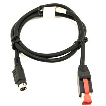
Encoder Feedback Cable with PUR Jacket for Digital Servo Loops
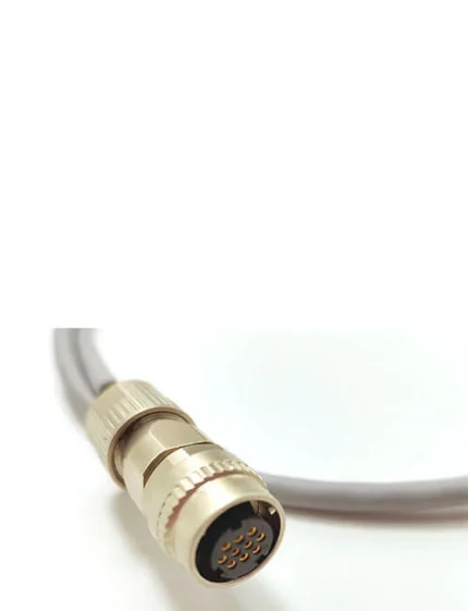
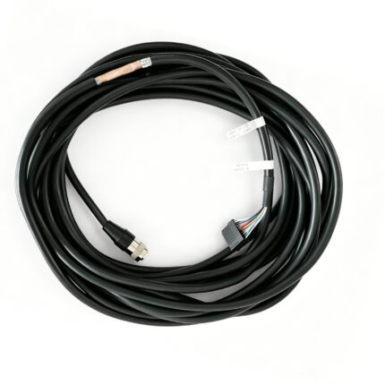
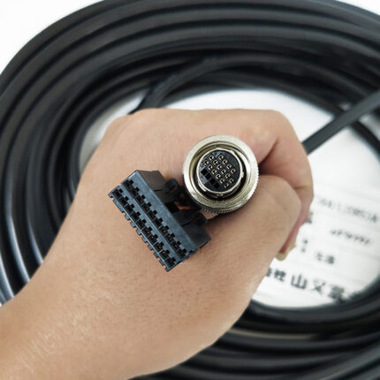
An encoder feedback cable built for the interface you actually run – EnDat, HIPERFACE DSL or BiSS-C – not a generic screened lead. PUR jacket for oil and coolant, pairing and screening set per protocol, terminated to your encoder and drive connectors.
Last updated: 13 September 2026
Overview
The feedback link between a motor encoder and its drive carries the position data the control loop reads every cycle. When it degrades the symptom is rarely a clean stop: it shows up as following error, position drift or nuisance trips that cost far more in machine time than the cable ever did. An encoder feedback cable has to be selected by the interface first, because the signal type decides the pairing, the screening and the core count before any of the mechanical numbers matter.
Key Specifications
| Product type | Digital encoder feedback cable |
|---|---|
| Jacket material | PUR, high-flex |
| Encoder interfaces | Compatible with EnDat, HIPERFACE DSL, BiSS-C |
| Older interfaces | Sin/cos 1 Vpp and SSI builds available for retrofit |
| Typical outer diameter | 6.8 mm or below digital, 11.0 mm or below sin-cos – to be confirmed |
| Flex life | Quoted around 5,000,000 cycles – to be confirmed |
| Torsion | Quoted plus or minus 30 degrees per meter – to be confirmed |
| Construction | Silicone-free, CFC-free, LABS-free |
Step 1: which feedback interface do you have
This is the selector. Everything downstream – core count, pairing, screen, diameter – follows from it. If you are replacing an existing lead, read the protocol off the encoder nameplate or the drive parameter, not off the connector shape, because several protocols share the same shell.
| Interface | What travels on the cable | Screening and pairing | Typical build |
|---|---|---|---|
| EnDat (2.2 / 3) | Bidirectional serial clock and data, plus power | Clock and data as a screened pair, power separately | Lower core count, small diameter |
| HIPERFACE DSL | Digital over the motor power-ish pair, plus power | Screened pair, tight impedance control | Compact, tolerant of longer runs |
| BiSS-C | Point-to-point serial, clock and data | Screened pair, continuous screen through the connector | Common on newer retrofit work |
| SSI | Clock and differential data, unidirectional | Two twisted pairs, both screened | Older installations, still common |
| Sin/cos 1 Vpp | Four analog sine and cosine tracks plus reference | Two screened pairs, analog – noisiest of the set | Largest diameter, most sensitive to routing |
Step 2: shielding and grounding
Getting the screening right is the difference between a cable that works and one that works until the spindle starts. Three choices cover most of it:
| Choice | When to use it | Trade-off |
|---|---|---|
| Overall braid only | Short, static runs away from motor power | Cheapest; high frequency performance is limited |
| Foil plus braid | The default for digital feedback in a machine tool | Costs more and is slightly stiffer |
| Foil plus braid, screen carried to the connector shell | Where the drive and the motor are separately grounded, or the run passes a drive cabinet | Requires the connector family to support a 360 degree screen termination |
The screen has to be continuous through the connector, not just present in the cable. A braid gathered into a pigtail and screwed to a pin is an antenna at the frequencies these interfaces run at, and it is the most common thing we find wrong on a failed installation.
Step 3: jacket and duty
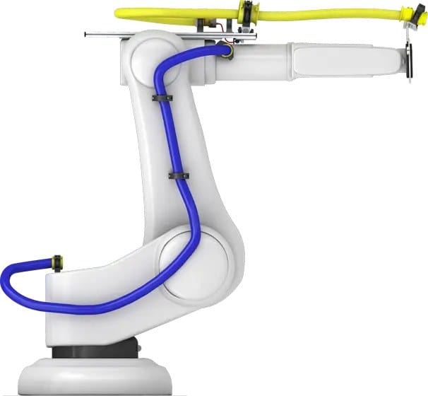
PUR is specified for oil and coolant contact on machine tools and for the abrasion a cable in a chain sees against its neighbors. Where the lead passes through a chain or a moving arm, tell us the travel and the cycle rate so the construction is sized for it rather than quoting a static cable into a dynamic job. Silicone-free, CFC-free and LABS-free construction is standard, which matters in paint shop areas where a contaminated cable ruins a panel finish.
Digital replacements for older wiring
Most retrofit enquiries start with an existing sin/cos or SSI run being upgraded to a digital interface, or with a lead that has been spliced one time too many. We build the replacement to the encoder side and drive side connectors of the existing machine, so the swap is mechanical rather than a redesign. Public competitor data for this class quotes an overall diameter of 6.8 mm or below for digital, incremental and SSI builds and 11.0 mm or below for sin-cos builds; those are recorded as a lead and still need to be measured on our production tooling.
Test methods on record
Oil resistance is referenced against the DIN EN 60811-404 method and flame behavior against IEC 60332-1-2. We do not publish either as a passed result until the supplier test report for the actual batch is in our hands; until then treat both as an engineering target you can ask us about. The flex life and torsion figures in the table come from the same place and are handled the same way.
Typical applications for this encoder feedback cable
- Machine tool axes where the feedback link runs through a drag chain
- Replacement leads for KUKA and FANUC arms, alongside our FANUC robot encoder cable and KUKA robot encoder cable
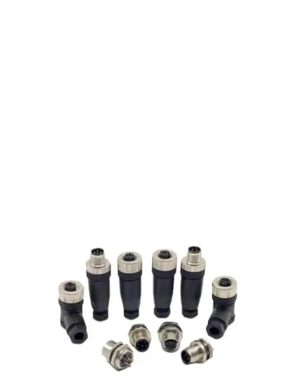
- Servo drops terminated in M23 screw lock cable assemblies
- Paint shop areas needing silicone-free construction
- New builds where the whole axis runs on one hybrid servo cable instead
How to specify your build
- Encoder type and interface – read it off the nameplate, not the connector.
- Drive model, so we match the drive side shell and pinout.
- Length and routing – fixed, chain, or moving arm, with travel and cycle rate.
- Screening – whether the screen has to be carried to the connector shell.
- Environment – oil, coolant, paint shop, temperature.
Workmanship and testing
Assembly and inspection follow IPC/WHMA-A-620 Class 3 workmanship criteria under our ISO 9001 quality management system, and every unit passes 100% continuity and pinout testing before it is packed. Conductor range is 32 to 12 AWG. Where an ingress rating is specified we can quote seal checking on the production batch.
Custom builds and ordering
Prototype builds start from 5 pcs and ship in 3 working days; production orders start at MOQ 500 pcs and ship 14 working days after approval. New overmold tooling adds about 10 working days. OEM and ODM builds ship under your part number and labeling, with material certificates and first-article reports available on request.
Related assemblies
- OEM Servo Encoder Cable Cross-Reference by Machine Family
- M23 Screw Lock Cable for Servo Motor Power and Encoder Feedback
- FANUC Robot Encoder Cable A660 Series Compatible
- KUKA Robot Encoder Cable Compatible with 00-174-775
- Custom Servo Motor Cable Assembly
- Hybrid Servo Cable for One-Cable Solution Servo Drives
The feedback device itself is a rotary encoder; the protocol it speaks is what decides the build, and the values your assembly is verified to are the ones on your drawing.
Frequently Asked Questions
Can I tell the interface from the connector?
No, and that is the usual trap. Several protocols share the same shell. Read it off the encoder nameplate or the drive parameter.
Do I need the screen carried to the connector shell?
If the drive and the motor are separately grounded, or the run passes a drive cabinet, yes. A pigtailed screen is an antenna at these frequencies.
Can you replace a sin/cos run with a digital one?
Only if the encoder and the drive both support the digital interface. Where they do not, we build the sin/cos replacement instead, with the larger diameter that analog tracks need.
What is the minimum order?
Prototypes start from 5 pcs and ship in 3 working days. Production runs start at 500 pcs and ship 14 working days after approval.
| Product type | Digital encoder feedback cable |
|---|---|
| Jacket material | PUR, high-flex |
| Encoder interfaces | Compatible with EnDat, HIPERFACE DSL, BiSS-C |
| Typical outer diameter | 6.8 mm or below digital, 11.0 mm or below sin-cos – to be confirmed |
| Flex life | Quoted around 5,000,000 cycles – to be confirmed |
| Torsion | Quoted plus or minus 30 degrees per meter – to be confirmed |
| Construction | Silicone-free, CFC-free, LABS-free |
| Older interfaces | Sin/cos 1 Vpp and SSI builds available for retrofit |