OBD-II 16-Pin to DB9 CAN Bus Diagnostic Cable, 25 ft
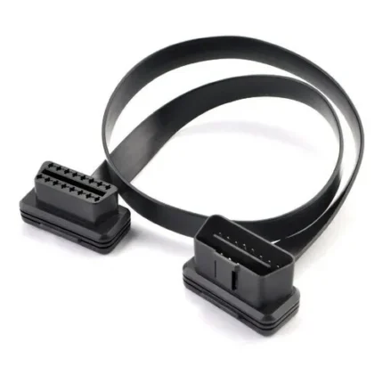
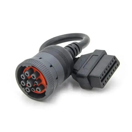
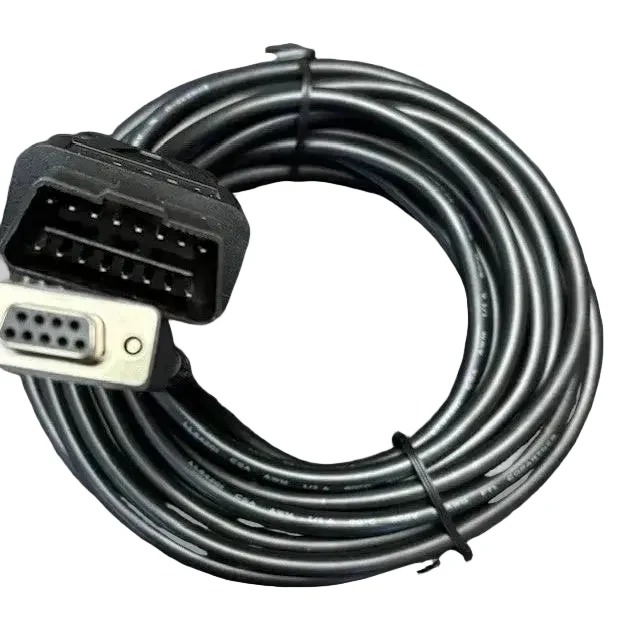
A db9 can bus cable running 25 ft (7.6 m) from a J1962 16-pin plug to a DB9 socket, for CAN logging and reverse-engineering work from a bench rather than a footwell. Passive and shielded, wired to the pinout you specify.
Overview
A db9 can bus cable at 25 ft (7.6 m) exists for one reason: somebody wants the laptop on a bench or a trolley instead of on the passenger floor. One end is a J1962 16-pin male plug for the vehicle, the other a DB9 female socket for the CAN interface or serial adapter. It is a passive cable, so it does no protocol conversion and does not care whether you are logging SAE J1939 traffic on a truck or ISO 15765 diagnostics on a car: the bus, the bit rate and the message set all come from the vehicle and the tool. What the cable does contribute is length, and at 7.6 m length stops being free.
Key Specifications
| Cable Type | CAN Bus Diagnostic Cable |
|---|---|
| Connector A | OBD-II J1962 16-Pin Male |
| Connector B | DB9 Female |
| Length | 25 ft (7.6 m) |
| Protocol | SAE J1939 / ISO 15765 CAN |
| Function | Passive cable, no protocol conversion |
| Shielding | Stated per your drawing |
| Conductor size | Stated per your drawing |
| Testing | 100% continuity and pinout check before packing |
The DB9 pinout is a convention, not a law
There is no single DB9 pin assignment for CAN, and this is where most “my cable does not work” stories start. The CAN in Automation DS-102 recommendation is the most widely followed, but plenty of interface vendors ship something else on pins 3, 5 and 9. Read the pinout your interface documents, then order the cable to match it rather than hoping they agree.
| DB9 pin | CiA DS-102 assignment | What you will also meet in the field |
|---|---|---|
| 2 | CAN low | CAN low on most tools |
| 3 | CAN ground | Sometimes ground, sometimes unused |
| 5 | CAN shield, optional | Sometimes CAN low on older interfaces |
| 7 | CAN high | CAN high on most tools |
| 9 | CAN supply, optional | Sometimes battery positive, sometimes unconnected |
| 1, 4, 6, 8 | Reserved | Vendor-defined on some hardware |
25 ft is a long stub: what that does to a CAN segment
A vehicle network is designed as a trunk with a terminating resistor at each end and short stubs tapping onto it. Your cable is one more stub, and the stub length guidance usually quoted for CAN scales roughly in inverse proportion to the bit rate: fractions of a meter at the fastest rates, a meter or two at 250 kbit/s. At 7.6 m you are outside all of it. In practice these leads work because the vehicle network itself is short and properly terminated and because most long-run logging happens at 250 kbit/s or below. If you need full margin at 500 kbit/s, put a short lead at the port and run the distance on USB or Ethernet instead.
| Bit rate | Stub length typically quoted | What 7.6 m means for you |
|---|---|---|
| 500 kbit/s | Well under a meter | Use a short lead and extend on the host side |
| 250 kbit/s | A meter or two | The usual working range for a 25 ft logging run |
| 125 kbit/s and below | Several meters | Comfortable, and the reason single-wire and legacy work tolerates long leads |
| Any rate | The twist must reach the contact | Untwisting the pair at the DB9 costs you more than the length does |
Power over pin 16: size the conductor or lose the voltage
A passive cable that carries battery power to an interface needs a conductor sized for the round trip, which is twice the one-way length. The figures below are industry-standard copper resistance values at 20 C for a single conductor over a 7.6 m run and back again, and they show why a signal-gauge power pair is the wrong choice at this length.
| AWG | Resistance per meter at 20 C | Round trip over 7.6 m | Drop at 1 A |
|---|---|---|---|
| 24 | 84 mOhm | 1.28 ohm | 1.28 V |
| 22 | 53 mOhm | 0.81 ohm | 0.81 V |
| 20 | 33 mOhm | 0.51 ohm | 0.51 V |
| 18 | 21 mOhm | 0.32 ohm | 0.32 V |
Read that as a method rather than a promise: take your interface current, multiply by the round trip resistance, and see what is left at the far end of a 12 V or 24 V system. The conductor your cable is built with is the one stated on your drawing.
Construction
- J1962 16-pin male plug at the vehicle, DB9 female socket at the tool.
- CAN pair kept twisted up to the contact, with the drain terminated at the connector end.
- Shield construction stated on your drawing; foil plus braid is the usual answer for long runs.
- Conductor cross section selected for the round trip, not just for the current.
- Overmolded strain relief at both bodies, because a 25 ft lead gets dragged.
How to specify your build
- The DB9 pinout your interface expects – a photo of the manual page is enough.
- Whether power is carried, and the current the interface draws.
- Conductor cross section for the power pair, using the round trip.
- Shielding – and whether the drain floats at one end.
- Length if 25 ft is not what the job needs.
Typical applications for this db9 can bus cable
- Fleet diagnostics with the interface hardware on a trolley beside the vehicle
- Reverse engineering where bus traffic has to be captured over a full duty cycle, alongside a Type 2 green 9-pin J1939 cable
- Bench logging on commercial vehicles, with a J1939 9-pin Y splitter keeping a telematics device online
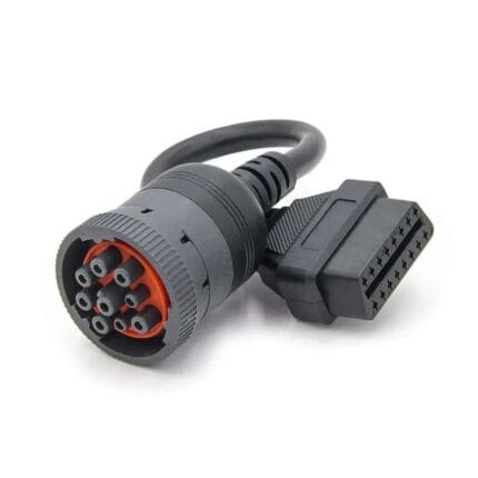
- Mixed fleets that still carry legacy tooling, paired with the black 9-pin J1939 Type 1 adapter
- Industrial CAN work where the same interface reaches an M12 CAN bus cordset on a machine
Workmanship and testing
ISO 9001 covers the system and IPC/WHMA-A-620 Class 3 covers the work on OBD-II 16-Pin builds, across 32 to 12 AWG. continuity and pinout are tested on each OBD-II unit before it is packed, and seal checking is quoted whenever an ingress rating is on the drawing.
Material declarations against RoHS and REACH are issued per project, alongside the dimensional and electrical reports agreed at quotation; see certifications, compliance and material declarations. Where your drawing names a UL style or another approval, the build follows your drawing and ships with the supporting document rather than a claim of our own. Overmold tooling for this part is designed and cut in our own tool room under the overmold tooling we build in-house, so the tool belongs to your program and a revision is a machining job rather than a new negotiation. More background: what changes on vehicle harness builds.
Custom builds and ordering
OBD-II 16-Pin lots run from 1 to 50 pcs, out in 3 working days; volume starts at MOQ 500 pcs shipping 14 working days after approval. Tooling not already held adds around 10 working days. Your part number and labeling go on OBD-II shipments, and material certificates and first-article reports can be supplied.
Related CAN and diagnostic leads
- SAE J1939 OBD2 Diagnostic Cable, Type 2 Green 9-Pin
- J1939 9-Pin Y Splitter Cable for ELD and GPS Trackers
- Black 9-Pin J1939 Type 1 Adapter to OBD2 16-Pin Socket
- OBD2 Type B Cable for Medium-Duty Truck Fleets
- DB50 to DB25 DTE Serial Cable
Full ranges: automotive cable and wire harness and signal and data cables.
Frequently Asked Questions
<div class="
For a related configuration, see the OBD-II 16-Pin Female to 3-Pin Diagnostic Lead Cable.
hkw-faq”>
Does this cable convert J1939 to something my laptop understands?
No. It is passive. The protocol work happens in your interface and your software; the cable only carries the two bus lines, power and ground.
Why is my DB9 pinout different from the table?
Because there is no single standard for a DB9 CAN pinout. DS-102 is the common recommendation, but check your interface documentation and order to that.
Will 25 ft work at 500 kbit/s?
Sometimes, and it depends on how much margin the vehicle network has. If you need guaranteed margin at the higher rate, use a short lead at the port and extend on the host side.
Can I power my interface from the vehicle through this cable?
Yes, and plenty of people do. Size the power pair for the round trip at 7.6 m, or you will be troubleshooting a voltage problem that looks like a bus problem.
| Cable Type | CAN Bus Diagnostic Cable |
|---|---|
| Connector A | OBD-II J1962 16-Pin Male |
| Connector B | DB9 Female |
| Length | 25 ft (7.6 m) |
| Protocol | SAE J1939 / ISO 15765 CAN |
| Function | Passive cable, no protocol conversion |
| Shielding | Stated per your drawing |
| Conductor size | Stated per your drawing |
| Testing | 100% continuity and pinout check before packing |