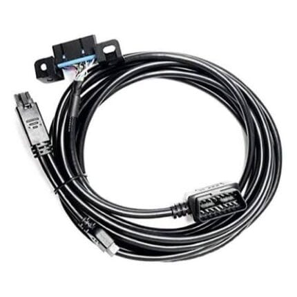
OBD-II 16-Pin to USB BMW INPA K+CAN Diagnostic Cable
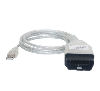
An obd2 bmw inpa cable with a J1962 16-pin plug to USB Type-A, for BMW INPA and K+CAN work with an external interface module. Passive lead, braided shield under a transparent jacket, built to the pinout you send.
Overview
An obd2 bmw inpa cable is the passive half of a two-part tool. One end is a J1962 16-pin male plug for the vehicle, the other a USB Type-A plug for the host, and the cable itself contains no electronics: no bridge chip, no K-line transceiver, no CAN controller. Those live on the external interface module this lead pairs with, and that module is not included. What the cable contributes is the wiring between the port and the module, and a braided shield under a transparent jacket so you can see the shielding is there instead of taking it on trust. BMW is a trademark of its owner; we supply compatible cable assemblies and are not an authorized distributor.
Key Specifications
| Cable Type | Passive Diagnostic Cable |
|---|---|
| Connector A | OBD-II J1962 16-Pin Male |
| Connector B | USB Type-A Male |
| Application | BMW INPA / K+CAN Diagnostics |
| Jacket | Transparent, over a braided shield |
| Active electronics | Not included; external interface module required |
| Length | Stated per your drawing |
| Testing | 100% continuity and pinout check before packing |
Cable, interface module, software: three different things
Almost every disappointed buyer of this kind of lead has conflated three separate parts. Sorting them out makes the purchasing decision obvious and removes most of the support questions.
| Part | What it does | Included here |
|---|---|---|
| This cable | Carries the vehicle side signals and the shield between the port and the module | Yes |
| External interface module | USB to serial bridge, K-line transceiver and CAN controller; the active electronics | No – supplied separately |
| Host software | Drives the session: fault codes, actuator tests, coding, live data | No – you supply it |
| The vehicle | Decides which protocol is on the pins and answers or stays silent | No |
K-line and CAN sit on different pins, and both matter here
The reason this lead is built for K+CAN work rather than for one protocol is history: the same marque used ISO 9141 serial diagnostics on older modules and moved to CAN later, so a workshop lead has to carry both. Which one the session actually runs on is decided by the module and the vehicle, not by the copper.
| Link | Where it sits on the 16-pin plug | What it serves | Notes |
|---|---|---|---|
| K line | Pin 7, ISO 9141-2 and ISO 14230-4 | Older modules and legacy diagnostic sessions | Slow by modern standards; still the only way into some units |
| CAN high / CAN low | Pins 6 and 14, ISO 15765-4 | Later modules and faster session work | Keep the pair twisted up to the contact |
| Battery positive | Pin 16 | Powers the interface module | Fused on the vehicle; check the rating |
| Chassis and signal ground | Pins 4 and 5 | Return and reference | Carry both rather than sharing one |
| L line | Pin 15 | Initialization on some older protocols | Often unused on later vehicles |
Two USB limits people forget
USB is not an infinite cable. A passive run is limited by the specification to a few meters before the signal integrity and the voltage drop stop being guaranteed, so a lead like this is a bench or footwell part, not a way to put the laptop in the next room. The second limit is power: the module draws its supply from the host port unless it also takes power from the vehicle, and a port that is already feeding a hub and a dongle may not have the current to spare. If the interface browns out or drops out, a powered hub is the first thing to try.
Why the braid is worth being able to see
The transparent jacket is not cosmetics. A diagnostic lead runs past coil packs, injector drivers and alternator wiring, and an unshielded run picks up exactly the kind of noise that turns a clean session into one that fails on the same module every time. With a transparent jacket you can confirm the braid and its coverage at a glance, which is worth more than a specification line you have to trust.
Construction
- J1962 16-pin male plug to USB Type-A male, straight through, no active components.
- Braided shield under a transparent jacket, with the drain terminated at the connector end.
- Stranded conductors, cross section stated on your drawing.
- Overmolded strain relief at both ends, which is where this type of lead fails first.
- Optional ferrite or a second shield layer where the host end sits next to other hardware.
How to specify your build
- Which pins the module needs – send the pinout it documents.
- Whether the module takes power from the vehicle or from USB, or both.
- Length, kept within what a passive USB run supports.
- Shielding – braid coverage and whether the drain floats at one end.
- Quantity, and whether you want them bagged with your part number.
Typical applications for this obd2 bmw inpa cable
- Independent specialists running factory-style tooling on a workshop laptop
- Fault code retrieval, adaptation resets and actuator tests on older modules, with an OBD2 extension flat cable to keep the port clear
- Live data logging where the laptop sits in the passenger footwell, paired with an OBD2 splitter and USB charger lead
- Bench setups where the vehicle side comes from a J1962 female to ECU board harness
- Workshops standardizing on one host, next to a car USB-C data cable for the laptop end
Workmanship and testing
Terminations on OBD-II 16-Pin builds run from 32 to 12 AWG, and the work is held to IPC/WHMA-A-620 Class 3 inside an ISO 9001 system. Every OBD-II unit is checked for continuity and pinout before packing, and seal checking is quoted whenever an ingress rating is on the drawing.
RoHS and REACH declarations are provided per project together with the agreed test reports; the documentation scope is listed under certifications and compliance. If your drawing specifies a UL style, we build to that drawing and supply the UL reference with the shipment instead of substituting an equivalent. The molded body is shot on our own presses; material choice and bond behavior follow the process described under overmold materials and injection parameters. More background: what changes on vehicle harness builds. Any tooling we cut for this part stays yours, maintained in our own tool room under your part reference.
Custom builds and ordering
OBD-II 16-Pin prototypes start from 1 to 50 pcs and ship in 3 working days; series supply starts at 500 pcs and takes 14 working days after sample sign-off. Tooling not already held adds around 10 working days. OBD-II orders ship under your part number and labeling material certificates and first-article reports are available on request.
Related diagnostic leads
- OBD2 Extension Flat Cable, 16-Pin Male to Female
- OBD2 Splitter USB Charger Cable, 16-Pin Pass-Through
- 16-Pin OBDII Y Splitter Extension Cable, Heavy-Duty Extender
- Car USB-C Data Cable with Right Angle Plug
- 16-Pin J1962F OBD2 Female Connector to ECU Board Harness
Full ranges: automotive cable and wire harness and signal and data cables.
Frequently Asked Questions
Does this cable work on its own?
No. It is the passive half. You need an external interface module with the active electronics, and the host software that drives the session.
Is it an original or authorized part?
No. It is a compatible cable assembly we build to the pinout you send. The vehicle marque name is used only to describe what the lead is made to fit.
Why does my session drop out?
Start with power. If the module draws from the host USB port, try a powered hub. Then check the shield and the drain termination, and keep the run away from ignition components.
Can I have a longer cable?
Within reason. A passive USB run is limited by the specification to a few meters, so beyond that the answer is a longer host-side extension rather than a longer vehicle-side lead.
| Cable Type | Passive Diagnostic Cable |
|---|---|
| Connector A | OBD-II J1962 16-Pin Male |
| Connector B | USB Type-A Male |
| Application | BMW INPA / K+CAN Diagnostics |
| Jacket | Transparent, over a braided shield |
| Active electronics | Not included; external interface module required |
| Length | Stated per your drawing |
| Testing | 100% continuity and pinout check before packing |
Related products
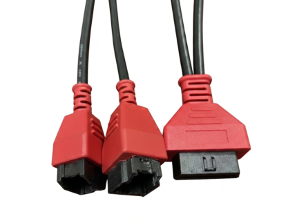
Heavy-Duty 9-Pin Industrial Diagnostic Cable Assembly
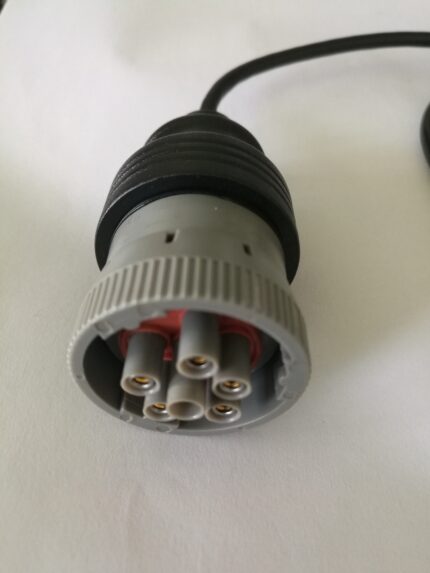
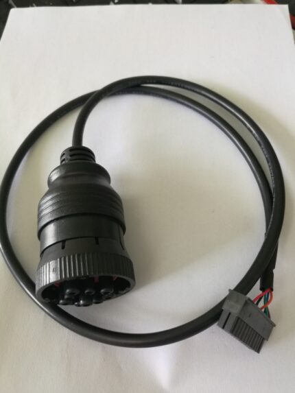
A heavy duty 9 pin cable with a 9-pin round industrial plug and a 14-pin 2x7 DIP bare end, for engine management diagnostics on trucks, marine diesel and heavy equipment benches. Verify the pinout against your service manual, since 9-pin assignments follow the engine maker rather than one specification.