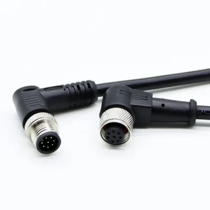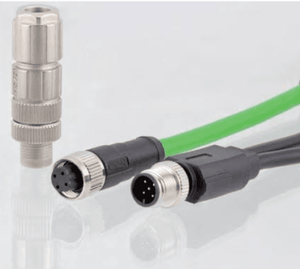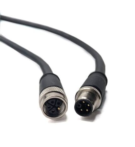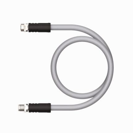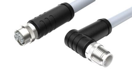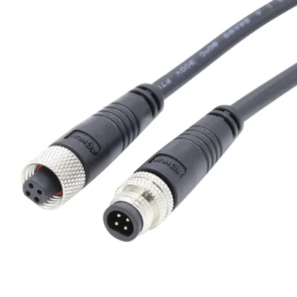
M12 3-Pin A-Coded Sensor / Actuator Extension Cable
This M12 actuator cable is the three-conductor A-coded extension used to replace or lengthen the last segment of a sensor drop without pulling new cable back to the cabinet. IEC 61076-2-101, IP67 mated, 60 V / 4 A, 24 AWG, PVC or PUR jacket, built to your pinout and length.
Overview
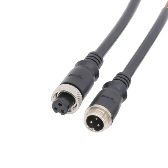
An M12 actuator cable with three conductors is the most common drop cord on a machine, and also the one most often mis-specified. Three positions carry everything a three-wire DC sensor needs: supply positive, supply negative, and the switched output. A fourth pin buys you nothing unless the sensor actually uses it, so the money goes into conductors you terminate rather than into capability you use. This one is built as a male-to-female extension in A-coding to IEC 61076-2-101, sealed to IP67 in the mated state, and made to the pinout, jacket and length on your drawing.
Key Specifications
| Connector | M12 3-pin A-coded male / female extension |
|---|---|
| Interface standard | IEC 61076-2-101 |
| Ingress rating | IP67 in the mated state |
| Rated voltage | 60 V AC/DC |
| Rated current | 4 A per pin |
| Conductor | 3 x 24 AWG stranded |
| Jacket | PVC or PUR |
| Operating temperature | -25 to +85 °C |
| Mating cycles | >100 |
Three, four, five or eight contacts
The A-coded family shares one shell and one thread, so the pin count is the only decision you have to make before the quote goes out. Count what the device needs, not what the catalog puts on the front page.
| Positions | Typical assignment | Choose it when |
|---|---|---|
| 3 | +V, 0 V and one switched output | Three-wire proximity switches, photoelectric sensors, simple limit switches |
| 4 | +V, 0 V and two outputs, or 4-wire device power | Sensors with NO plus NC outputs, 4-wire instruments |
| 5 | Power pair plus two signal or control conductors | Dual-output devices, ports that also carry a diagnostic line |
| 8 | Two devices in one shell, or power plus multiple signals | I/O blocks, compact multi-channel junction points |
| 12 | High density signal grouping | Encoder heads and valve blocks running many nets per run |
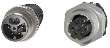
Reading a 3-pin A-coded face
The numbering is inherited from the four-position layout, which is why there is no pin 2 on a three-pin connector. Technicians who count clockwise from 1 get it wrong every time.
| Pin | Wire color | Function | Note |
|---|---|---|---|
| 1 | Brown | Supply positive | Typically 24 V DC on factory floor sensors |
| 3 | Blue | Supply negative | The common return, not a signal reference to be shared |
| 4 | Black | Switched output | Normally open or normally closed depending on the sensor |
We terminate to your wire set. If the sensor you are replacing used a different color code, send the existing cordset or a photo of the pin face and it will be built that way.
The face is only half the story, because the keyway around it decides what the plug will accept. For the whole picture rather than the three-pin case, the download center has a two-page coding reference covering every letter with its usual pole counts and applications.
PNP or NPN: why the cordset does not care
Sourcing and sinking sensors put different electronics behind the same three pins, so the copper is identical and only the load wiring changes. The cordset cannot be wrong here; the panel can. A common field fault is a replacement sensor with the opposite output polarity wired into a card configured for the original, which reads as a sensor that never switches. Before you blame the cable, check whether the PLC input is wired for the polarity the new device delivers, and confirm whether the input module expects a pull-up or a pull-down reference.
Extend or run a new home-run
The argument for an extension rather than a fresh cable back to the cabinet is arithmetic. A replacement sensor cable has to be pulled through the same conduit, past the same cable track and around the same corners, and it usually means opening a gland that has been sealed for years. An extension changes only the last segment: unplug at the existing coupling, insert the male-to-female cordset, and the panel side stays untouched. The cost of that choice is one additional mated joint in the sealing path, so both halves have to be rated for the environment and made up properly, hand-tight and then a fraction more with a spanner on the metal hex only.
How far can the run go
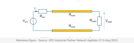
The 4 A per pin figure is what the contact pair is rated for, not what the whole drop can carry forever. Long runs are limited by conductor resistance and the voltage drop the load will tolerate, and both get worse when several drops share a supply and when the cable sits in a warm tray next to other conductors.
| Question | What decides it | Where the number comes from |
|---|---|---|
| How much current does the load draw | Steady draw plus inrush at switch-on | Device datasheet, not the cable rating |
| How much drop can the load accept | Minimum operating voltage at the device | Stated per your drawing |
| How many conducting pins run together | Simultaneous load raises the bundle temperature | Confirm at order |
| What is the ambient temperature | Derating starts below the maximum conductor rating | Confirm at order |
| Is the run fixed or moving | Flex duty changes stranding and jacket choice | Stated per your drawing |
At the conductor sizes in this family the honest answer is usually measured rather than calculated at the desktop. Tell us the load current and the routed length and we will build on 24 AWG or quote a larger cross-section where the drop does not stack up.
Installation notes that prevent callbacks
Three habits account for most early failures. Supporting the harness within the first few hundred millimeters so the connector body carries no cable weight. Keeping the run out of the swarf and coolant stream, or specifying PUR when it cannot be routed away. And leaving service loop rather than tension: a cordset pulled straight will work on the day you commission it and start dropping the signal when the machine gets warm and everything moves.
Typical applications for this M12 actuator cable
- Extending the last segment to a proximity or photoelectric switch without pulling new cable
- Replacing a jacket that has been cut by swarf or softened by coolant, keeping the panel side intact
- Standardizing mixed length runs onto one part number per machine section
- Temporary or diagnostic tethering during commissioning and retrofit work
- Sensor drops on packaging, printing and assembly equipment with distributed field I/O
How to specify your build
- Ends – male to female, straight or right-angle, and the clocking direction of the angle.
- Length, measured along the routed path rather than point to point.
- Jacket – PVC for dry enclosures, PUR where oil, coolant or UV is present.
- Wire set, if it differs from the standard colors above.
- Fixed or flexing service, and the cycle rate if it moves.
- Quantity, and whether this is a prototype or a production release.
A photo of the existing cordset, a device part number, or a sketch with the two ends marked is enough for us to quote.
Workmanship and testing
M12 3-Pin A-Coded Sensor builds are made to IPC/WHMA-A-620 Class 3 workmanship inside an ISO 9001 system, over a 32 to 12 AWG range. continuity and pinout are verified on each M12 assembly before packing, and seal checking is quoted whenever an ingress rating is on the drawing.
RoHS and REACH declarations are provided per project together with the agreed test reports; the documentation scope is listed under certifications and compliance. If your drawing specifies a UL style, we build to that drawing and supply the UL reference with the shipment instead of substituting an equivalent. The strain relief and molded body are produced on tooling we cut ourselves see in-house mold making and overmold tooling so the tool is quoted separately, owned by you, and available for repeat runs years later. The wider context is covered under what automation programs ask for.
Custom builds and ordering
For M12 3-Pin A-Coded Sensor builds, prototypes run from 1 to 50 pcs with a 3 working day turnaround; volume orders begin at 500 pcs and ship 14 working days after approval. Tooling not already held adds around 10 working days. OEM and ODM M12 work ships under your part number and labeling, and material certificates and first-article reports are available on request.
Related M8 and M12 assemblies
- M12 IO-Link Cable, Master to Device Drop
- M12 A-Code 4-Pin Y-Splitter Sensor / Actuator Cable
- M12 8-Pin A-Coded IP67 Waterproof Extension Cable
- M8 3-Pin A-Coded Circular Connector Sensor / Actuator Cable
- M12 Drag Chain Cable, Continuous Flex Cordset
- M12 12 Pin Cable, High Density Cordset
Full range: circular M8 and M12 cable assemblies.
Frequently Asked Questions
Is a 3-pin extension the same as a 4-pin with one position missing?
No. The contact numbering keeps positions 1, 3 and 4 from the four-pin face, so the wire colors follow those numbers rather than a simple 1-2-3 sequence.
Can I use this on a device that sources rather than sinks its output?
Yes. The conductors are the same; what changes is how the input card is wired. Confirm the polarity the PLC input expects before ordering a replacement sensor.
How long a length can you build?
Any length you need, but tell us the load current. Long runs are limited by voltage drop, and we will quote a larger cross-section where 24 AWG is too small.
Will PUR survive cutting oil?
PUR handles oil and coolant far better than PVC, which is why we recommend it anywhere the jacket sits in the splash path. Tell us the exact medium if it is unusual.
What is the minimum order?
You can start from 1 to 50 pcs for evaluation and expect them in 3 working days. Series orders begin at 500 pcs and go out 14 working days after the sample is approved.
| Connector | M12 3-Pin A-Coded Male/Female |
|---|---|
| Standard | IEC 61076-2-101 |
| IP Rating | IP67 |
| Rated Voltage | 60 V AC/DC |
| Rated Current | 4 A per pin |
| Conductor | 3 x 24 AWG |
| Jacket | PVC / PUR |
| Operating Temperature | -25 to +85 °C |
| Mating Cycles | >100 |