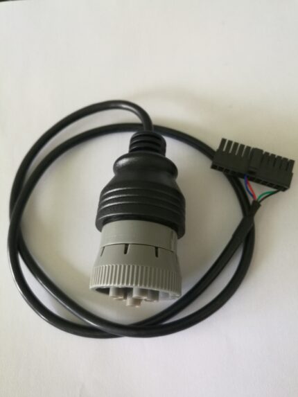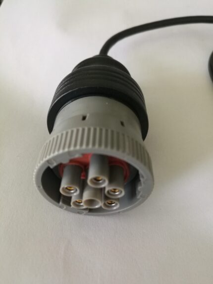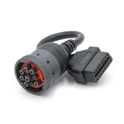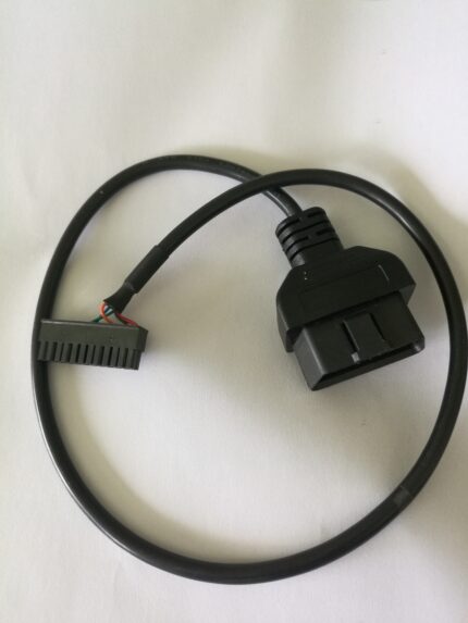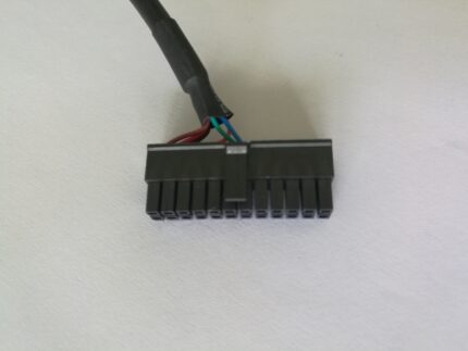
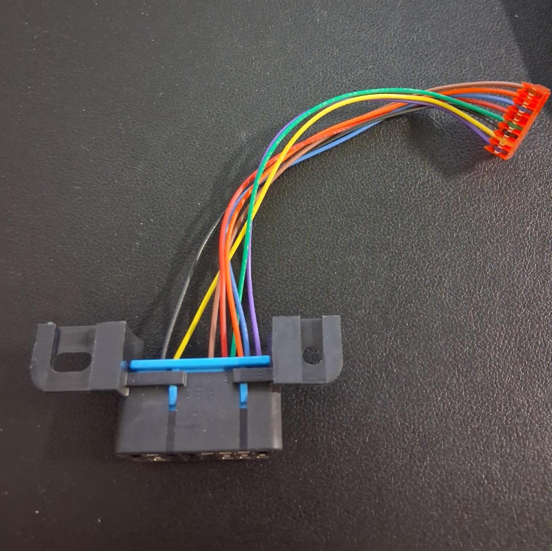
16 Pin J1962F OBD2 Female Connector to ECU board Tyco 8pin Wire harness 1ft
A 16 pin J1962F OBD2 ECU harness bridges the vehicle diagnostic port and the 8-position housing on an ECU or programming jig, at 1 ft as standard. Built to the pin-to-pin mapping you send, not to a rule of thumb.
Overview
A 16 pin J1962F OBD2 ECU harness exists because the connector on the car and the connector on the board were designed by two different groups of people with two different numbering habits. One end is the trapezoid 16-pin port every vehicle carries; the other is the compact 8-position housing on the ECU or on a programming jig. This harness bridges them at 1 ft so a bench stays tidy, and so nobody has to re-solder a pigtail every time a different ECU lands on the desk.
Key Specifications
| Connector A | 16-pin J1962F OBD2 female, panel or inline body |
|---|---|
| Connector B | Tyco 8-pin housing for the ECU board, or open leads |
| Length | 1 ft (30 cm) standard; OEM build to order |
| Conductor | 32 to 12 AWG, per build |
| Jacket | PVC standard; PUR for workshop use |
| Marking | Every lead numbered to the mating pin, to order |
| Build | Bench harness for flashing, programming and diagnosis |
Two ends, two numbering systems
The vehicle side follows SAE J1962, where the pins are numbered 1 to 8 across the top row and 9 to 16 across the bottom row as you look into the face of the port. The board side follows the connector maker, and on an 8-position housing the count usually runs around the face in a single circle with pin 1 marked by a keyway or a chamfer. There is no arithmetic relationship between the two: OBDII pin 6 does not become board pin 6. That is why this harness is always built from a written mapping, never from a rule of thumb. Background on the vehicle side of the standard sits in the OBD-II entry.
Which pins a bench actually uses
Most of the sixteen never get touched on a bench. A flash or a diagnostic session on a modern ECU needs power, ground and the CAN pair; everything else is protocol or manufacturer specific. The table is the industry-standard assignment, quoted as a reference — the harness you order is wired to the mapping you send and verified pin for pin.
| Pin(s) | Signal per SAE J1962 | Role on the bench |
|---|---|---|
| 4 | Chassis ground | Ground reference for the bench supply |
| 5 | Signal ground | Clean return for the data lines |
| 6 | CAN High (ISO 15765-4 and SAE J2284) | Primary bus on 2008-onward vehicles |
| 14 | CAN Low (ISO 15765-4 and SAE J2284) | Paired with pin 6; never swapped |
| 7 | K line (ISO 9141-2 and ISO 14230-4) | ISO protocol vehicles and older ECUs |
| 15 | L line (ISO 9141-2) | Wake-up line on legacy ISO builds |
| 16 | Battery positive | Bench supply feed, unswitched |
| 1, 3, 8, 9, 11, 12, 13 | Manufacturer discretion | Wired only when your ECU or tool needs them |
Choosing the board end
The board termination is where these harnesses are won or lost, because it is the end that has to survive being plugged and unplugged all day. Pick by what is already on the ECU or the jig:
| Board end | Best for | Where builds go wrong |
|---|---|---|
| Tyco 8-pin housing | Bench jigs that mate with a standard ECU header | Keyway and latch orientation must match the board receptacle |
| Open tinned leads | Breadboard work, screw terminals, flying probes | Needs a numbering legend or the build becomes a beeping job |
| DIP or pin header | Dev boards and programming sockets | Row pitch and pin 1 marker are the usual mistakes |
| Your housing | Production programming fixtures | Send the housing part number or a sample and we build to it |
The three mistakes that send harnesses back
- Mirrored face views. A pinout drawn looking into a plug is the mirror image of the same connector drawn from the back. Say which view your drawing uses, or send a photo of the mating face.
- Counting direction. Some makers count clockwise, some counter-clockwise, and on an 8-position housing both readings look plausible until the harness is plugged in.
- Gender swap. Male and female face views are mirror images too. Confirm which half is on the vehicle port and which is on the jig before ordering.
We build from the mapping you provide and check continuity and pinout against it on every unit, so a five-minute conversation about the face view saves a return shipment. If you would rather break the pins out to a screw terminal instead, our OBD-II 16-pin female to 14-pin DIP breakout cable does that job on the same vehicle interface.
Typical applications for this 16 pin J1962F OBD2 ECU harness
- Bench-mode ECU testing and fault reproduction off the vehicle
- ECU flashing, cloning and chip tuning jigs
- Immobilizer and key programming setups
- Automotive R&D labs and end-of-line programming fixtures
- Workshop diagnostics where the port needs to reach a board, alongside our OBD-II to DB9 CAN bus cable
How to specify your build
- The mapping — vehicle pin to board pin, written out, or a photo of both faces.
- Board end — Tyco 8-pin housing, pin header, open leads, or your housing.
- Keyway and latch orientation on the board housing.
- Length — 1 ft standard, longer for a bench with the supply at the back.
- Conductor gauge for the power pair versus the data pair.
- Marking — numbered sleeves, printed flags, or a legend card.
- Quantity, and whether the jig is a one-off or a repeat build.
Workmanship and testing
Workmanship on 16 Pin J1962F OBD2 builds follows IPC/WHMA-A-620 Class 3, the line is run under ISO 9001, and the termination range is 32 to 12 AWG. No 16 assembly is boxed before continuity and pinout are confirmed, and seal checking is quoted whenever an ingress rating is on the drawing.
Every production run can ship with RoHS and REACH declarations and the electrical report agreed at quotation; see certifications and material declarations. UL styles and other named approvals are built to drawing: we source to the style you specify and document it, rather than asserting a listing we do not hold. This assembly is built on the four lines covered under our assembly lines in Longgang, with nothing in the build handed to an undisclosed subcontractor. The wider context is covered under our automotive and EV work. Tooling is quoted separately, cut in-house rather than brokered out, and owned by you.
Custom builds and ordering
Quote 16 Pin J1962F OBD2 builds from 1 to 50 pcs and they ship in 3 working days. At volume the minimum is 500 pcs with 14 working days after approval. Tooling not already held adds around 10 working days. OEM and ODM 16 runs go out under your part number and labeling and material certificates and first-article reports are on offer.
Related diagnostic leads
- OBD-II 16-pin to 3-pin diagnostic lead cable
- OBD-II 16-pin to USB BMW INPA K+CAN cable
- 14-pin round to 14-pin DIP diagnostic adapter cable
- BMW 16-pin to 20-pin OBD diagnostic adapter cable
- 16 pin OBDII Y splitter extension cable
- OBD2 extension flat cable, 16-pin male to female ribbon lead
Full range: automotive cable and wire harness assemblies.
Frequently Asked Questions
Is this a pass-through or a breakout?
It is a breakout: the 16-pin vehicle interface on one end, the 8-position board housing on the other. If you need the pins on screw terminals or a header instead, we can terminate that way on the same build.
Can you wire only the pins my ECU uses?
Yes. A power, ground and CAN pair build is common and makes a thinner, more flexible lead. Spare conductors can be left in place for future protocols if you prefer.
Do I need to send a pinout drawing?
A pin-to-pin list is enough, and so is a clear photo of both mating faces if you are unsure. What we cannot do is guess between two mirrored readings.
Can the board end be a different housing?
Yes. Send the housing part number or a sample and we will build to it, including the keyway and latch orientation your receptacle expects.
What is the minimum order?
Quote 16 Pin J1962F OBD2 builds from 1 to 50 pcs and they ship in 3 working days. At volume the minimum is 500 pcs with 14 working days after approval.
| Connector A | 16-pin J1962F OBD2 female, panel or inline body |
|---|---|
| Connector B | Tyco 8-pin housing for the ECU board, or open leads |
| Length | 1 ft (30 cm) standard; OEM build to order |
| Conductor | 32 to 12 AWG, per build |
| Jacket | PVC standard; PUR for workshop use |
| Marking | Every lead numbered to the mating pin, to order |
| Build | Bench harness for flashing, programming and diagnosis |