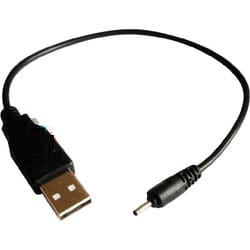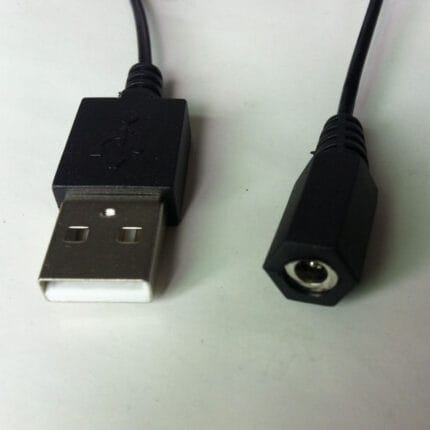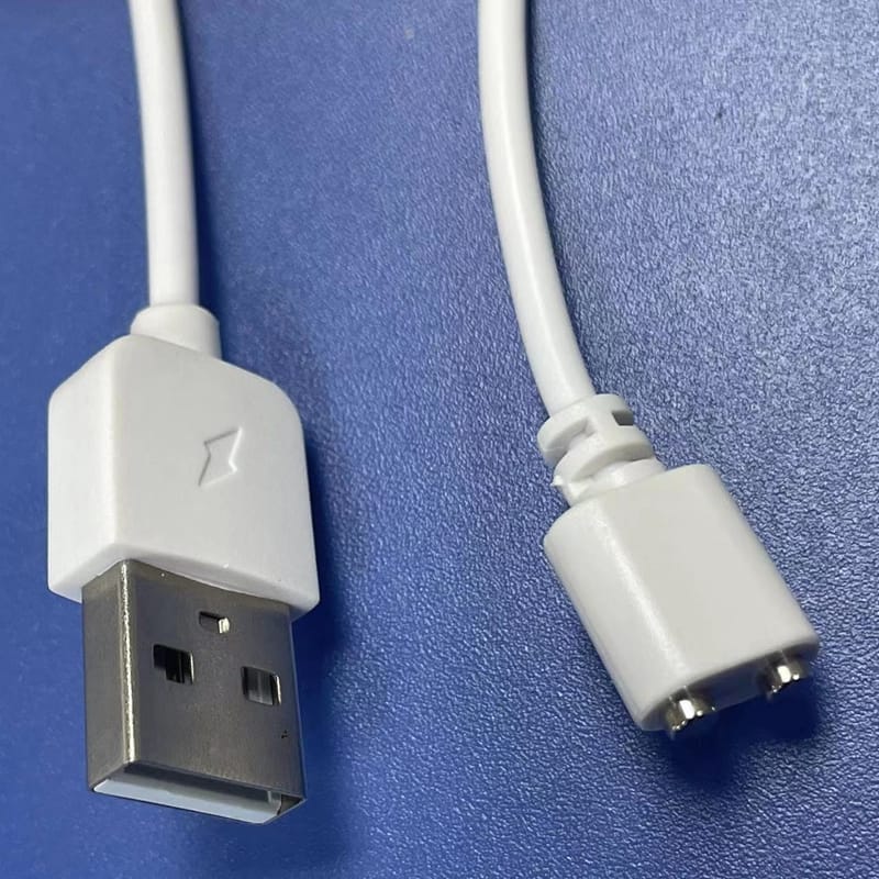
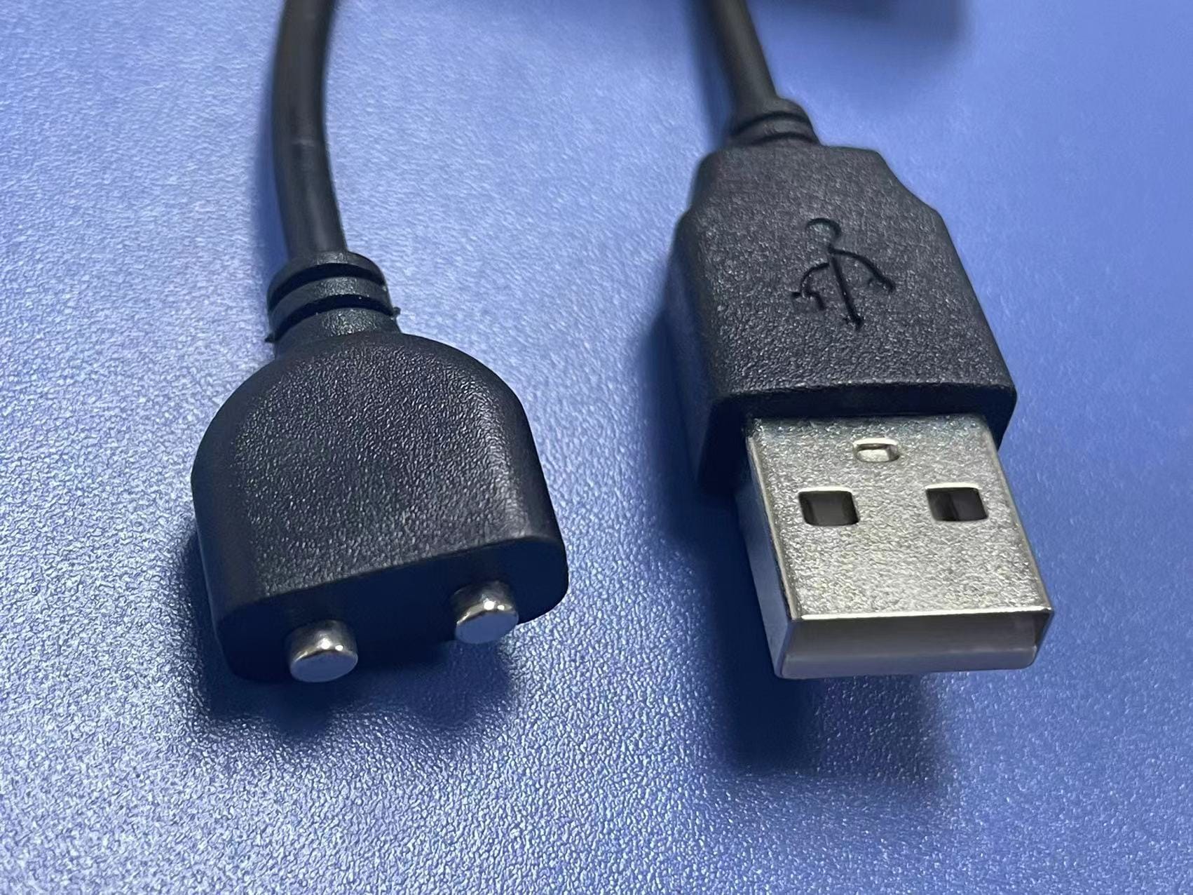
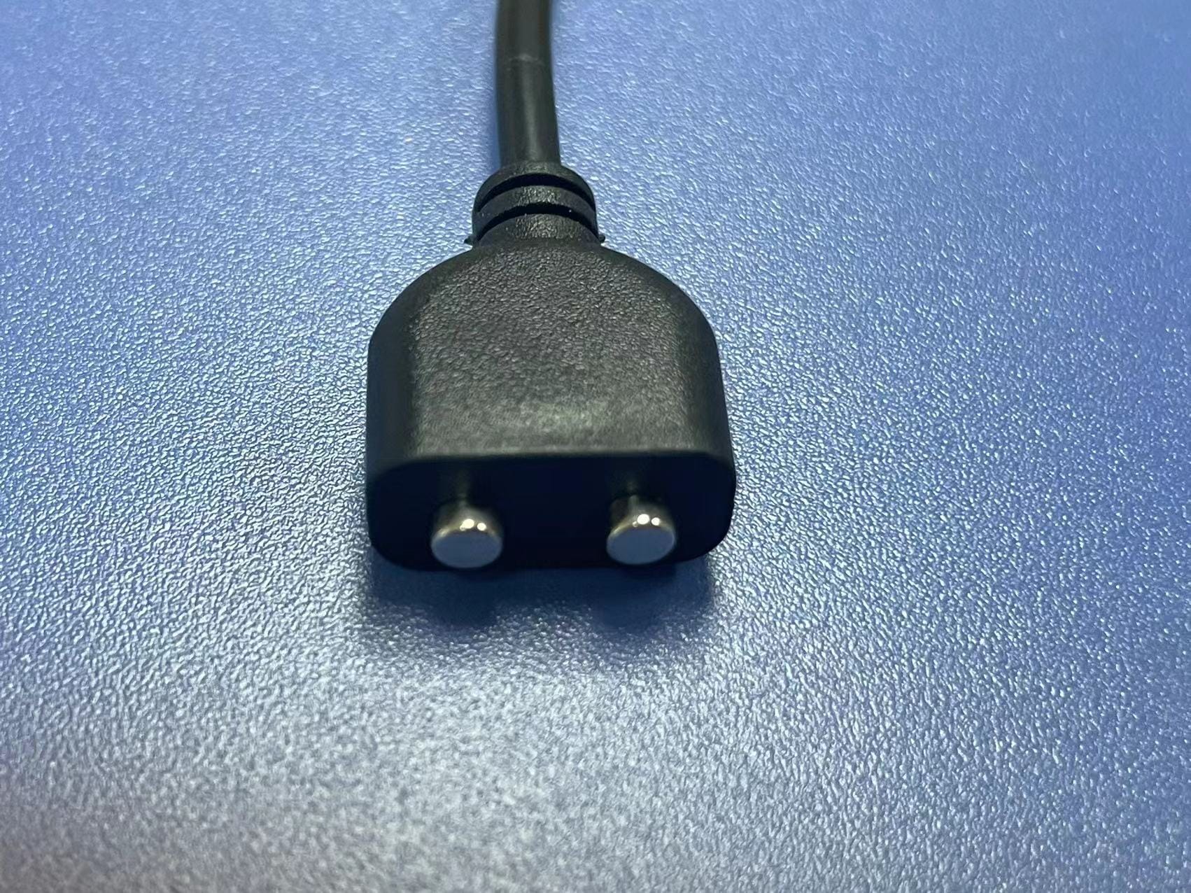
Square-Shape 2-Pin Magnetic Charging Cable
A magnetic 2pin square cable ends in a square-edge molded pogo head that users can orient by touch and that sits flush on a rectangular housing. Two contacts carry DC power only.
Built for charging cradles, wearable docks and small DC appliances where a breakaway joint protects the device port.
Overview
A magnetic 2pin square cable is a power-only lead that ends in a square-outline pogo head. The square shape is not styling: it gives the user an orientation they can feel in the dark, and it lets the head sit flush against a rectangular device housing instead of standing proud of it. Two contacts carry DC, and the magnetic joint releases when the lead is pulled, so a trip over the cable costs you a dropped charge rather than a bent device port. Host end is USB-A; the device side is a tip you specify.
Key Specifications
| Connector A | USB-A male, gold-plated contacts |
|---|---|
| Connector B | 2-pin pogo-pin magnetic head, square housing |
| Pin configuration | 2-pin (V+ / GND) |
| Contact resistance | <= 50 mOhm per pin at rated load |
| Mating cycles | 10,000 connect / disconnect minimum |
| Conductor | 2 x 24 AWG tinned copper, foil shielded with drain wire |
| Cable jacket | PVC, black or white, 3.0 mm OD typical |
| Length | 1 m standard; OEM on request |
| Head construction | One-shot injection mold, ABS / PC, matte finish, recessed magnet pocket |
| Strain relief | TPE boot exiting in line with the cable axis |
Why the head is square, and when round is the better answer
Square wins on two counts. First, orientation: a round magnetic head with two contacts can be offered up two ways, and one of them is wrong. A square outline removes the guess, which matters on a device that gets charged by feel – a bedside cradle, a wearable on a wrist, a handheld scanner dropped into a dock at the end of a shift. Second, clearance: where the device housing is itself rectangular, a square head lines up with the face and leaves no lip to catch on a pocket or a bag.
Round still wins where the device port is recessed in a round boss or where the user will approach the port from any angle. We tool both, and the choice is made on the device drawing rather than on a catalog picture.
What actually holds the head on
Four things decide whether a magnetic joint feels right in the hand and survives in the field. None of them is the magnet alone, which is why “stronger magnet” is usually the wrong fix for a head that falls off.
| Question | What decides it | What we need from you |
|---|---|---|
| Release force | Magnet grade plus the flat contact area of the housing face | Target pull-off force, or a sample device to match against |
| Contact resistance | Pogo spring force, plating, and the pad finish on the device tip | Rated load current, so the pin is sized to it |
| Alignment | Magnet polarity keying the head, plus the square outline | Device-side tip drawing or 3D model |
| Cycle life | Plating wear on the pogo tip and on the device pad | Expected mating cycles per day |
If the head releases too easily, the usual cause is not a weak magnet but a housing face that does not sit flat against the device – a curve, a raised bezel, or a label. Send a photo of the mating face and we will tell you whether the fix is in the mold or in the device housing.
Why a magnetic joint runs warmer than a solid barrel
Every pogo pin in the path adds resistance that a molded barrel plug does not have: a spring, a plunger and a contact face that meets a flat pad instead of a wrapped sleeve. The stated figure here is 50 mOhm per pin, and with two pins in series that is 0.1 Ohm before the cable itself contributes anything. The arithmetic below is worked from that stated per-pin figure so you can see what it costs at realistic loads; the values your assembly is built and verified to are the ones on your drawing.
| Load current | Drop across two pins at 50 mOhm each | Heat in the joint |
|---|---|---|
| 0.5 A | 0.05 V | 0.025 W |
| 1 A | 0.1 V | 0.1 W |
| 2 A | 0.2 V | 0.4 W |
Two consequences follow. At 5 V the drop is a real share of your budget, so the device sees less than the charger puts out – measure at the device, not at the USB port. And the heat lands in the head, which is the part touching the user. If your load sits above roughly 2 A, or if the head is enclosed so the heat cannot leave, move to the 4-pin variant and split the current across parallel contacts.
Polarity and pin spacing: the two numbers that decide fit
Specify both. Polarity is not only about which pin carries V+; it is also about which way the magnet lets the head seat. Reverse the magnet and the head flips 180 degrees, landing V+ on the ground pad. We key the magnet orientation to the pin layout on every build and verify it on the test fixture, but we need the device tip layout to key it against.
Pin spacing is the other half. Two-pin heads are quoted across a range of pitches, and a difference of a few tenths of a millimeter shows up as a head that snaps on and then intermittently drops the charge. Give us the center-to-center dimension from the tip drawing, or send the tip.
Typical applications for this magnetic 2pin square cable
- Charging cradles and docks for handheld terminals and scanners
- Wearable device charging where a low-profile rectangular head sits flush
- Replacement lead for a proprietary 2-pin magnetic system you no longer buy
- LED desk lamps, small fans and other low-current DC appliances
- Demo and retail display units, where the breakaway stops the unit being pulled off the shelf
How to specify your build
- Device tip drawing – pad layout, pin pitch and mounting, or a sample tip.
- Load current at the device, measured or from the label.
- Release force you want, or a sample to match.
- Housing size and color, and whether square or round.
- Cable length, jacket color and jacket material.
- Magnet polarity, if the device tip already exists.
- Quantity, and whether this is evaluation or production.
Workmanship and testing
Workmanship on Square-Shape 2-Pin Magnetic Charging builds follows IPC/WHMA-A-620 Class 3, the line is run under ISO 9001, and the termination range is 32 to 12 AWG. Every Square-Shape unit is checked for continuity and pinout before packing, and seal checking is quoted whenever an ingress rating is on the drawing.
Material declarations against RoHS and REACH are issued per project, alongside the dimensional and electrical reports agreed at quotation; see certifications, compliance and material declarations. Where your drawing names a UL style or another approval, the build follows your drawing and ships with the supporting document rather than a claim of our own. The strain relief and molded body are produced on tooling we cut ourselves see in-house mold making and overmold tooling so the tool is quoted separately, owned by you, and available for repeat runs years later. Related reading: cable assemblies for marine and outdoor equipment.
Custom builds and ordering
Prototypes are quoted from 1 to 50 pcs and ship within 3 working days. Volume production starts at 500 pcs with a 14 working day lead time after approval, and about 10 working days more when a new tool is needed. Private labeling carries your part number, and material certificates with first-article reports are available on request.
Related DC and magnetic assemblies
- Heart-Shape 2-Pin Magnetic Charging Cable
- DC 5.5 x 2.1 mm Magnetic Charging Cable
- Magnetic Pogo Pin Cable USB-C for Medical and Wearable Devices
- USB Type-C Magnetic Charging Cable
- 240 W Magnetic USB-C Charging Cable, 16-Pin Rotatable
- USB-C PD Trigger Cable to DC 5.5×2.1mm
Full range: DC plug power cable assemblies.
Frequently Asked Questions
Is this a data cable?
No. Two pins carry V+ and GND only. If you need USB 2.0 data alongside power, or more than about 2 A, use a 4-pin head – the pin count is the deciding factor, not the housing shape.
Can you match a magnetic tip we already use?
Usually yes. Send a sample tip or its drawing and we will quote against the same pad layout, pitch and magnet orientation. Where the existing head is a shape we do not hold, a new mold is required.
Why does my head get warm during charging?
Contact resistance in the pogo pins. At the stated 50 mOhm per pin and two pins in series, a 2 A load puts about 0.4 W into the joint. That is normally harmless in open air and a problem inside an enclosure. Measure the drop and reduce the current or move to four pins.
How long does the plating last?
The head is specified to a 10,000 cycle minimum. Real life depends on how the pad on your device tip is finished – a hard gold pad wears far better than bare copper with a flash.
| Connector A | USB-A male, gold-plated contacts |
|---|---|
| Connector B | 2-pin pogo-pin magnetic head, square housing |
| Pin Configuration | 2-pin (V+ / GND) |
| Contact Resistance | <= 50 mOhm per pin at rated load |
| Mating Cycles | 10,000 connect / disconnect minimum |
| Cable Jacket | PVC, black or white, 3.0 mm OD typical |
| Length | 1 m standard; OEM on request |
| Magnet Polarity | Keyed to the pin layout; set at order |