USB-C PD Trigger Cable to DC 5.5×2.1mm – 5V / 9V / 12V / 15V / 20V / 28V, 100W
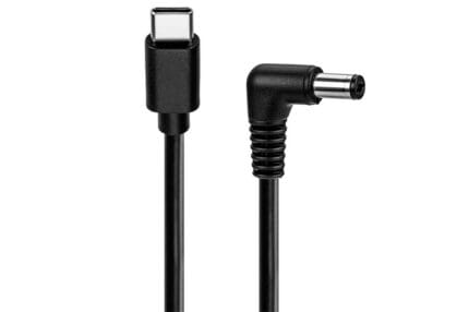
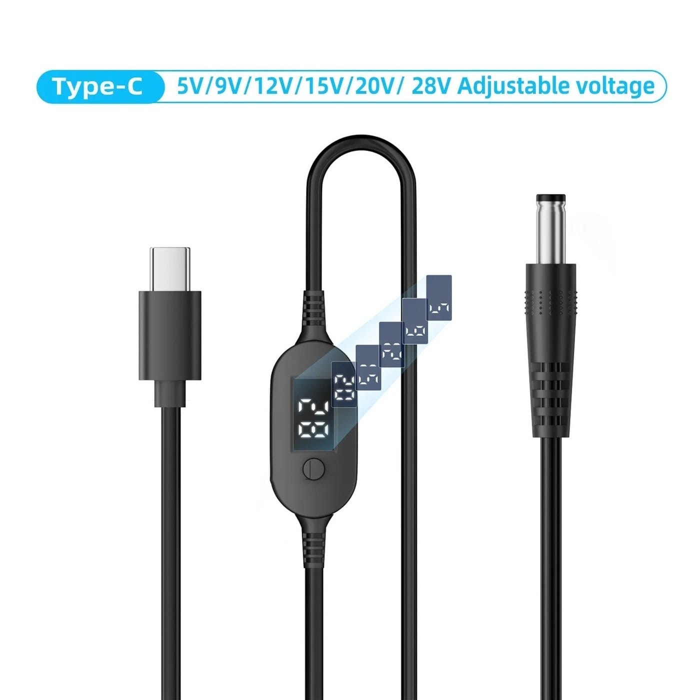
A usb-c pd trigger cable with a built-in voltage display: switch-selected 5, 9, 12, 15, 20 or 28 V out of any USB-C PD charger, presented on a 5.5×2.1mm barrel. 18 AWG, 1 m or 2 m, right-angle option. PD 2.0 / 3.0 only.
Overview
This USB-C PD trigger cable asks a USB-C charger or power bank for a fixed voltage
and presents it on a DC barrel plug, and then shows you which voltage it got. That display is the point
of this version: on a bench or in a kit bag, “is it actually putting out 12 V?” is a question worth
being able to answer without a meter. Six steps are available — 5 V, 9 V, 12 V, 15 V, 20 V and 28 V —
selected by a switch on the trigger head, and the same head tells you what came back from the charger.
Key Specifications
| Cable type | USB-C PD trigger to DC barrel, with voltage display |
|---|---|
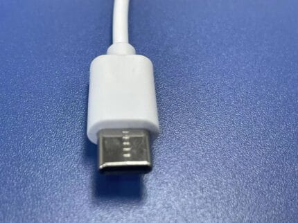
| Connector A | USB-C plug (PD 2.0 / 3.0) |
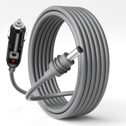
| Connector B | DC barrel 5.5 x 2.1 mm, center positive |
| Max power | Up to 100 W, charger dependent |
| Conductor | 18 AWG |
| Length | 1 m / 2 m, right-angle option |
| Output voltage | 5 / 9 / 12 / 15 / 20 / 28 V, switch-selected |
| Protocol | PD 2.0 / 3.0 only; Quick Charge not supported |
Voltage steps and what each one is for
The switch on the head selects which entry in the charger’s advertised list the trigger asks for.
The step has to exist on the charger, or the request gets nothing.
| Step | Typical load | What to know |
|---|---|---|
| 5 V | Small peripherals, hobby boards, fans | The default every USB-C source offers, so it always works |
| 9 V | Routers, modems, some ONTs | A common step on phone chargers and power banks |
| 12 V | Cameras, LED controllers, display terminals, most 12 V gear | The step most builds are ordered at; check your charger lists it |
| 15 V | Mini PCs, higher power single-board computers | Less common on small chargers — check the label |
| 20 V | Laptop-class loads, monitors | The top of the standard power range, so most 60 W chargers and up offer it |
| 28 V | Higher power DC loads | An extended power range step — the charger and the cable both have to support EPR before it appears |
That last row catches people out. 28 V sits above the standard power range ceiling of 20 V, so the
charger has to advertise an extended power range profile and the cable on the source side has to be an
EPR cable for it to be offered at all. On an ordinary PD 3.0 charger the switch will simply not produce
28 V, and the display will show you that immediately.
Why the display is there
A trigger cable fails silently. Ask for a voltage the charger does not offer and many triggers simply
stay at 5 V, which looks identical to a working cable at a glance — until the router does not boot. The
inline readout removes the guesswork in the three situations that come up most: confirming the output
before an expensive load is connected, seeing at once whether the charger in hand offers the step you
need, and separating a charger problem from a load problem in seconds without a meter.
Gauge and voltage drop on the barrel run
The aspect that decides whether this cable works in a real installation is not the wattage on the
headline — it is how much voltage arrives at the plug. On a 12 V run the limiting factor is usually
drop, not the current rating of the wire. The figures below are nominal resistance values for stranded
copper at 20 ℃, for estimating only, and both conductors count, so a 2 m cable is 4 m of copper
in series. Conductor sizes follow the American wire gauge scale, where a smaller number means a thicker
conductor.
| Conductor | Nominal resistance per meter | Round-trip at 1 m | Round-trip at 2 m |
|---|---|---|---|
| 18 AWG | About 21 mΩ | About 42 mΩ | About 84 mΩ |
| 16 AWG | About 13 mΩ | About 26 mΩ | About 52 mΩ |
| 14 AWG | About 8.3 mΩ | About 17 mΩ | About 33 mΩ |
Multiply the round-trip figure by the load current to get the drop in volts. At 2 A on a 2 m 18 AWG
build that is roughly a sixth of a volt — fine. At 5 A on the same cable it is approaching half a volt,
which is the difference between a router that runs and one that browns out on transmit. The drop your
assembly is built and verified to is the figure stated on your drawing; send us the load current and the
length and we will size the conductor. A 12 V load with a narrow input range is the case that most often
needs a step up in gauge.
Barrel size, polarity and the load end
The load end is a 5.5 x 2.1 mm barrel, center positive, which covers the great majority of network
and small computing gear. Where your load takes something else, the same build is quoted with a 5.5 x
2.5 mm or a 4.0 x 1.7 mm plug, and with a right-angle barrel for wall-mounted equipment. Check the
polarity symbol on the device before applying power.
PD only, and what that means
This is a Power Delivery device: it speaks PD 2.0 and PD 3.0 and nothing else. On a Quick Charge only
port it will not negotiate and the output stays at the default 5 V, and the display shows it.
Typical applications for this USB-C PD trigger cable
- Replacing a failed OEM adapter for a router, ONT or modem without waiting on a branded spare
- Running a mini PC or single-board computer from a power bank during field work
- Powering 12 V LED controllers and small displays from a USB-C PD supply
- Emergency comms kits where one charger has to serve everything and the voltage has to be certain
- Bench and repair work, where the readout doubles as a quick charger tester
- Paired with a DC plug adapter set where the load takes a different barrel
How to specify your build
- Voltage steps — which of the six you need, and which is the default position.
- Barrel size and orientation — 5.5 x 2.1 mm, 5.5 x 2.5 mm or 4.0 x 1.7 mm, straight or right-angle.
- Length and conductor — 1 m or 2 m in 18 AWG, or a heavier gauge for long, high-current runs.
- Display type — the readout format and where the head sits on the cable.
- Jacket, color and print.
- Quantity, and whether samples are needed first.
Workmanship and testing
IPC/WHMA-A-620 Class 3 is the workmanship bar for USB-C PD Trigger builds, and ISO 9001 is the system behind the line, from 32 to 12 AWG. No USB-C assembly is boxed before continuity and pinout are confirmed, and seal checking is quoted whenever an ingress rating is on the drawing.
Material declarations against RoHS and REACH are issued per project, alongside the dimensional and electrical reports agreed at quotation; see certifications, compliance and material declarations. Where your drawing names a UL style or another approval, the build follows your drawing and ships with the supporting document rather than a claim of our own. Where this build needs an overmold, the tool is designed, cut and maintained in our own shop under in-house mold making and overmold tooling, and it is never used for another customer’s program. Related reading: cable assemblies for marine and outdoor equipment.
Related power leads
- USB-C PD Trigger Power Cable to DC 5.5×2.1mm Barrel
- USB-C PD Charging Cable 240 W PD 3.1 EPR, Braided
- USB-C Power Display Cable 240 W PD 3.1 with Digital W/V/A Readout
- IP67 DC to USB-C Cable, 5.5×2.1mm Barrel Power Lead
- 14 AWG DC Barrel Pigtail Cable 5.5×2.1mm to Bare Wire
Full range: DC Plug Power Cable.
Frequently Asked Questions
Why does the display show 5 V when I selected 12 V?
The charger does not offer that step, or it does not speak PD at all. Try a charger whose label lists 12 V output, and check it is PD rather than Quick Charge only.
Does the 28 V position work on every charger?
No. 28 V is an extended power range step, so the charger has to advertise it and the source-side cable has to be EPR rated. On an ordinary PD 3.0 charger it will not appear.
Can I change the voltage after delivery?
On the switch-selected version, yes, within the steps built into the head. On a fixed-voltage build, no — the profile is set at the trigger.
Is 18 AWG enough?
For 1 m and 2 m at typical router and mini PC loads, yes. For a longer run or a load that pulls close to the charger limit, step up a gauge — drop is what makes loads brown out.
What is the minimum order?
Five pieces is the prototype minimum for USB-C PD Trigger builds, shipping in 3 working days; the production minimum is 500 pcs, delivered 14 working days after sample approval.
| Cable type | USB-C PD trigger to DC barrel, with voltage display |
|---|---|
| Connector A | USB-C plug (PD 2.0 / 3.0) |
| Connector B | DC barrel 5.5 x 2.1 mm, center positive |
| Max power | Up to 100 W (charger dependent) |
| Conductor | 18 AWG |
| Length | 1 m / 2 m, right-angle option |
| Output voltage | 5 / 9 / 12 / 15 / 20 / 28 V, switch-selected |
| Protocol | PD 2.0 / 3.0 only; Quick Charge not supported |
Related products
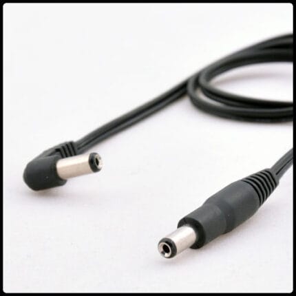
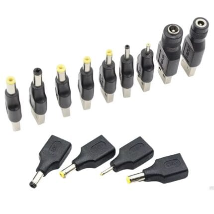
DC Barrel Adapter Kit – 5521 / 5525 / 4017 / 3513 / 1.35mm / 2.5mm, 6-Piece
A dc barrel adapter kit covering 5.5x2.1, 5.5x2.5, 4.0x1.7, 3.5x1.35 and 2.5 mm in six molded female-to-male adapters, so one supply covers a mixed estate. Center positive throughout, with nickel-plated brass contacts. Measure the socket pin with a caliper before ordering: the outer shell is identical across three of these five sizes. Bagged with a size card, or boxed with a printed insert.