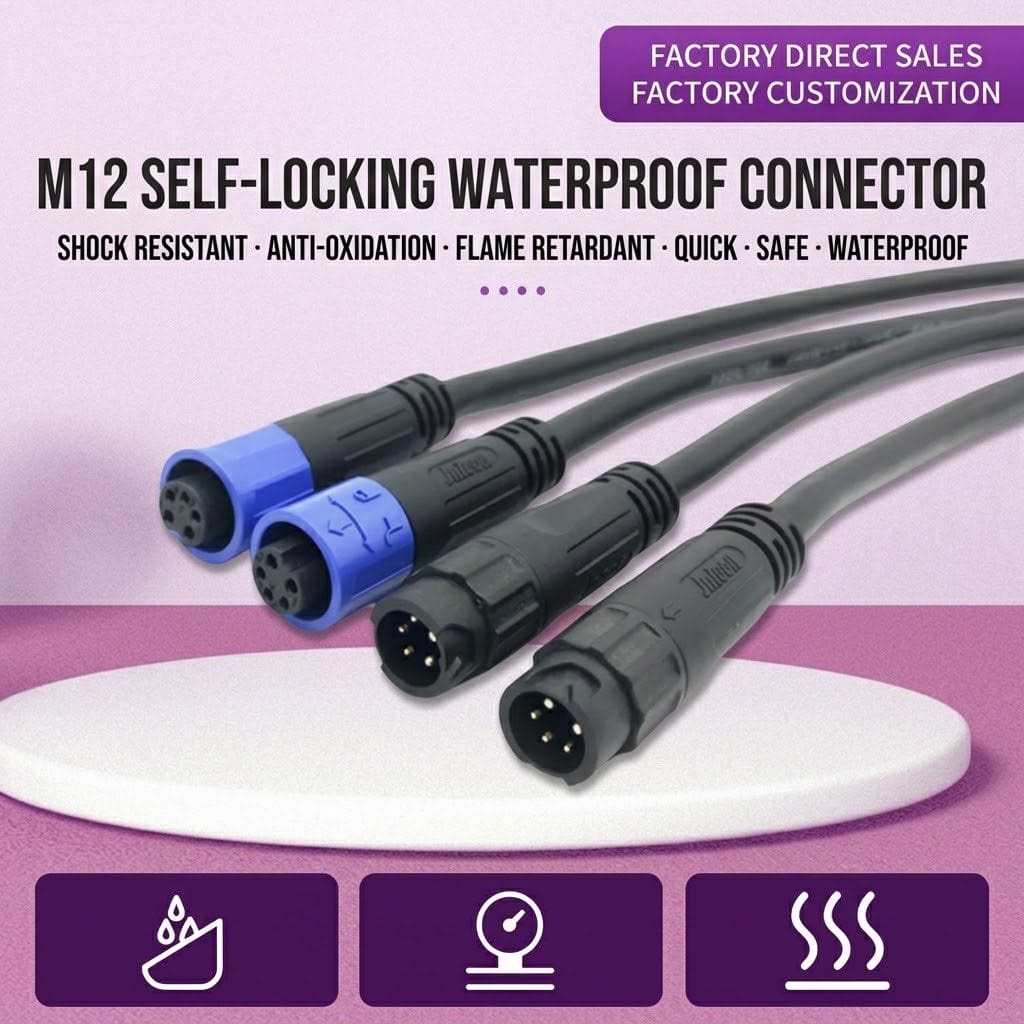
M12 A-Code Push-Pull Sensor Cable, IP67
This m12 push pull cable keeps the A-coded sensor pinout the industry knows and swaps the screw thread for a push-pull coupling: press the shells together and the retaining latch locks, so a connection that took several turns now takes a second.
Overview
This m12 push pull cable keeps the A-coded sensor pinout the industry knows and swaps the screw thread for a push-pull coupling: press the shells together and the retaining latch locks, so a connection that took several turns now takes a second.
Push-pull coupling changes the service economics of sensor wiring. Inside a machine cell where a technician swaps cameras or I/O blocks every shift, the latch seating in one motion means faster changeovers and no dropped, cross-threaded coupling nuts falling into the enclosure. The A-coded contact layout stays standard, so electrical pinouts do not change.
Key Specifications
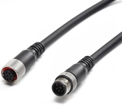
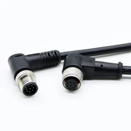
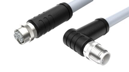
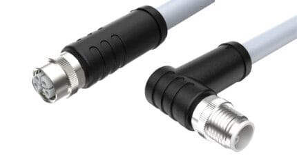
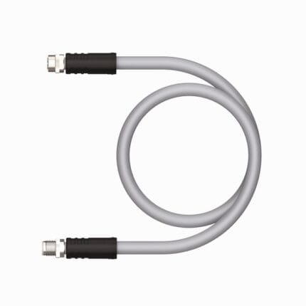
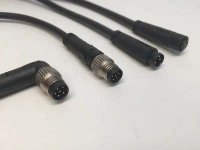
The table below lists the configuration shown in the product photo.
Push-Pull Versus Threaded: What Actually Changes
The mechanical difference is the whole point of this part. A conventional M12 cordset uses a knurled coupling nut that threads onto the receptacle, which means every connection involves several rotations, correct start of the thread, and enough clearance around the port to swing a hand or a tool. Do that badly in a hurry and the result is a cross-threaded nut or a joint left finger-tight, which is where most intermittent sensor faults begin.
Push-pull replaces those turns with axial travel. The plug slides onto the receptacle and a retaining latch engages at the end of the stroke, giving the same retention in one motion. Nothing is threaded, so there is nothing to cross and nothing to under-tighten. In mountings where access is poor — a sensor buried inside a frame channel, a camera behind a guard panel, an I/O block on a door — that is often the difference between a connection a technician makes correctly every time and one that gets done badly once in ten.
What “A-Coded” Buys You
A-coding is the most widely used member of the M12 family, and it is the coding suppliers mean when they list an M12 connector without saying more. Its contact layout is defined in IEC 61076-2-101 alongside B, C and D coding, and it spans the widest pin-count range of any M12 coding, from small three-contact sensor connectors through to high-density 12 and 17 position inserts. Published classification tables place it in the low-voltage signal class used for proximity sensors, actuators, IO-Link devices and general DC power.
That breadth is useful and slightly dangerous. Because A-coded shells exist with so many contact counts, “A-coded” alone tells you almost nothing about pinout. Ordering by thread size and family name is how mismatched cordsets get bought; the reliable identifiers are the coding letter plus the exact pin count.
Construction and Materials
Both connectors are overmolded with the latch collar integrated into the shell, and the internal seal keeps the contact cavity protected when the pair is mated. The round jacket stays flexible for the drag and flex that sensor drops normally see, and the mating face keys positively so the connectors cannot be pushed together misaligned. What overmolding buys at the construction level, and what it costs in tooling and flexibility, is set out in our field wireable connector guide.
The latch collar is part of the overmolded shell rather than an added part, so repeated mating wears the molded body instead of a clip. The internal seal is compressed by the mating face, and the keyway keeps the insert from being forced in rotated.
Typical Applications
Use it on machine vision cameras that are swapped between stations, robot-end tooling that changes weekly, door-mounted I/O blocks serviced during changeovers, and any A-coded sensor point where speed of connection matters more than a screwed thread.
Changeover-intensive cells benefit most. On a line that runs short batches, the cameras and sensors that define each product run get moved every time the line switches over, and the accumulated time spent spinning coupling nuts is real machine downtime. Replacing those drops with latch couplings removes the step and, more importantly, removes the variation in how well it gets done.
Quick-change tooling at the robot wrist is the second big user. Tool changers already index mechanically, so the wiring connection is usually the slow part of a swap, and wrist space is exactly where a hand cannot get enough clearance to turn a nut.
Guard-door I/O blocks, mobile test rigs and rental equipment round out the list — anywhere the same connection gets made and broken repeatedly by people whose main job is something else.
The Four-Pin into Five-Pin Trap
One mechanical quirk is worth knowing before you order. In the A-coded family a four-pin plug will physically mate with a five-pin receptacle, leaving the fifth contact unused. It fits, nothing is damaged, and in a three-wire sensor installation the outcome may be identical to what you intended — but where the fifth position carries a second output, a shield drain or a diagnostic line, that “successful” mating silently removes the function.
The practical defense is boring and effective: specify the pin count explicitly on the purchase line and check it against the device datasheet, not against the shape of the connector.
Compatibility and Fitment
The contact layout follows the standard M12 A-code pinout, while the push-pull latch mates only with matching push-pull counterparts; it does not mate with threaded M12 ports. Confirm your device port is the push-pull style before ordering.
That last sentence causes more returns than anything else in this family. Push-pull and threaded M12 look similar at a glance and share the same coding letters, but the shells are not interchangeable. If the equipment you are wiring has a threaded receptacle, specify the threaded version instead — the electrical result is the same and only the retention differs.
Where Push-Pull Is the Wrong Answer
Latch couplings are excellent where connections are made often and wrongly. They are less clearly better where the cordset is mated once and left alone for years, because a threaded nut still gives a tighter, more tamper-resistant joint and tolerates a wider range of shell tolerances.
Continuous high-vibration mountings deserve the same caution. A hand-tightened thread, a properly torqued thread and a latch all differ in what they survive; if your concern is a circuit that must never loosen, say so when you inquire and we will recommend the coupling that suits the mounting rather than the one that is quickest to install.
Installation Notes for Latch Couplings
Seat the plug until the latch clicks and then pull gently back on the body to confirm engagement. A half-seated latch looks connected and behaves like a loose contact.
Because there is no thread to take up slack, avoid routing the cable so its weight or bend pulls sideways on the coupling. Support the drop nearby so the latch carries retention only, not cable strain.
Keep the mating faces covered whenever a branch is left open. The seal that delivers IP67 performance only works across a mated pair — an unmated plug sitting in coolant mist is not protected by anything.
Custom Builds and Ordering
Pin counts, lengths and straight or right-angle exits are produced to order. Share the device schedule and we will quote the cordset mix. Prototype and sample lots run from 1 to 50 pieces and ship in 3 working days; production orders start at 500 pieces per part number and ship 14 working days after approval, with new overmold tooling adding about 10 working days.
Packaging and Shipping
Each cordset ships bagged with the latch protected; OEM labels and bulk packs are available.
Quality and Compliance
Continuity and latch engagement are checked on every assembly, and the overmold is inspected for complete sealing fill. See the IEC 61076-2-101 circular connector standard for the governing interface specification.
Material declarations against RoHS and REACH are issued per project, alongside the dimensional and electrical reports agreed at quotation; see certifications, compliance and material declarations. Where your drawing names a UL style or another approval, the build follows your drawing and ships with the supporting document rather than a claim of our own. Sealing follows the insert, gasket and overmold-bond method described under waterproof sealing design and validation, so the rating comes from the joint design rather than from the connector datasheet alone. Related reading: our industrial automation work. Tooling for this build is cut in our own tool room and belongs to your program, so a repeat run years later starts from the same tool.
Frequently Asked Questions
Will this mate with a normal threaded M12 port? No. Push-pull shells only latch into push-pull counterparts. Check the receptacle style before ordering.
Does the A-coded pinout change? No. Only the coupling mechanism differs; contact assignment and coding follow the standard A-code layout.
Can I mix push-pull and threaded cordsets on one machine? Yes, as long as each mating pair matches at both ends. Machines often mix them by design.
Are right-angle versions available? Yes. Straight and ninety-degree exits are both built to order.
Related Cable Ranges
Browse the related ranges: Circular M-Series Cable Assemblies Signal and Data Cables Screw-Lock Molded Cable.
For smaller sensors and tighter spaces compare the IP67 right-angle M8 sensor cable and the threaded M8 screw-lock cable.
| Coding | A-coded contact layout |
|---|---|
| Locking | Push-pull quick coupling, tool-free |
| Application | Sensors, cameras, drives, I/O blocks |
| Ingress Rating | IP67 when mated |
| Orientation | Straight and right-angle options shown |
| Construction | Overmolded, circular jacket |