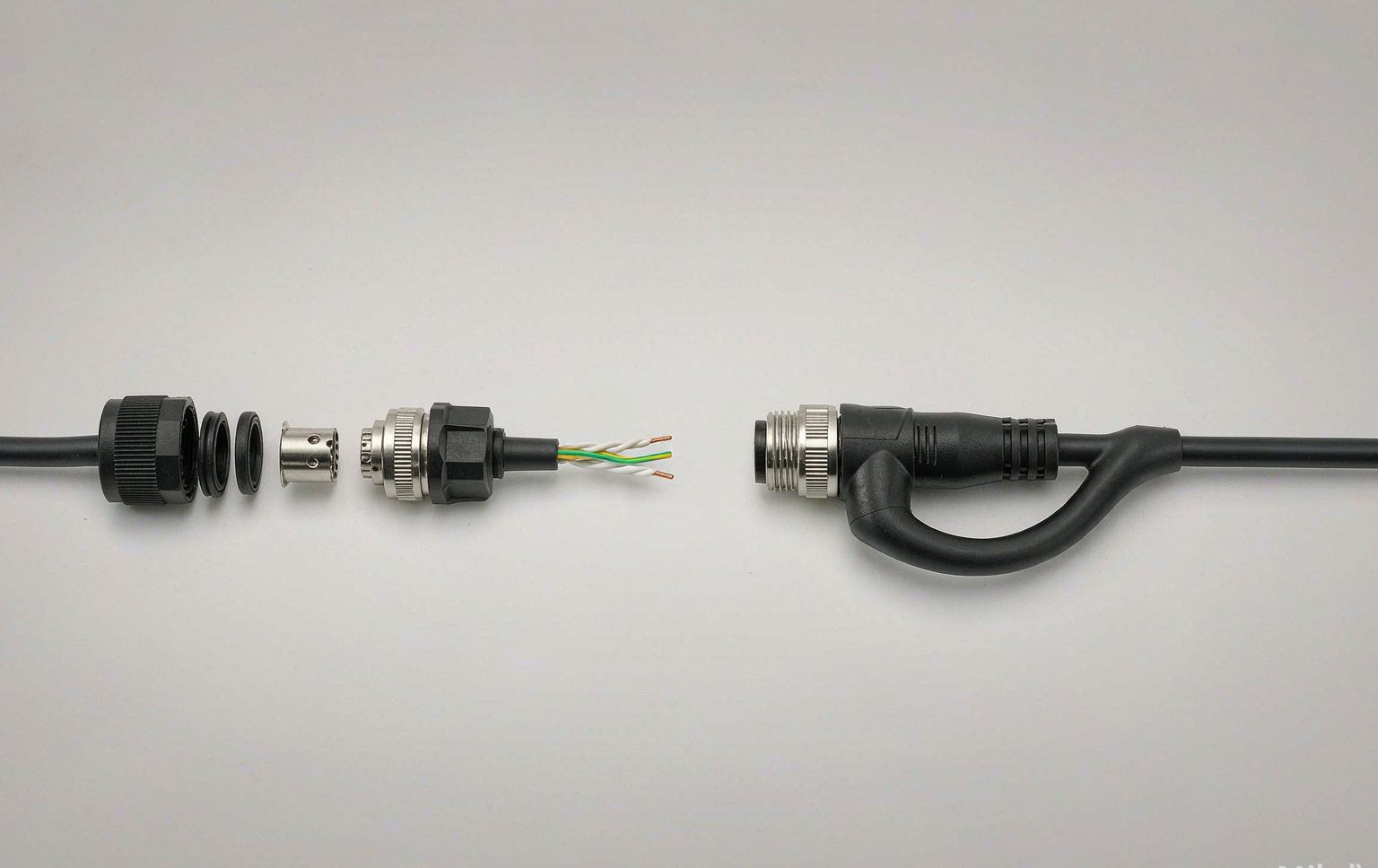
Every cable assembly starts with the same three questions: which contact, which cable, and who puts them together. A field wireable connector hands that last job to the installer; a molded cable assembly keeps it in the factory. Both options end in the same mating face, both are sold with the same IP code, and on a quote they can differ by only a couple of dollars. They are not the same product, and the difference is not cosmetic.
This is a comparison of the two constructions on the four things that actually move: how many sealing joints each one creates, what the IP rating on the datasheet really certifies, what happens at the termination, and what the assembly costs once somebody has to build it. The numbers below are engineering inputs you can replace with your own — the method is the point.
Field wireable connector or molded cordset: one interface, two constructions
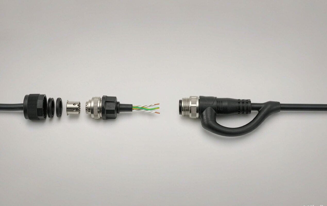
A molded (overmolded) cordset arrives finished. The contact is crimped to the conductor, the assembly is placed in a tool, and molten jacket material is injected around it so that the connector shell, the strain relief and the cable exit become one continuous part. Nothing behind the mating face can be taken apart.
A field-wireable connector arrives as parts: contacts or a termination block, an insert, a shell, a cable gland and a set of seals. The installer cuts the cable to length, terminates it, stacks the parts and tightens the gland. Three termination styles dominate — screw-clamp, crimp-and-insert, and insulation-displacement (IDC) — and they behave differently enough that the choice matters as much as the connector itself (Section 5).
The mating interface is shared. An M12 field-wireable connector and an M12 molded cordset mate to the same receptacle defined by the same interface standard, IEC 61076-2-101, so electrically and mechanically they are interchangeable once assembled. Everything that separates them lives behind the panel: the seals, the termination and the work. That is also why a screw-lock coupling can sit on either construction — see connector locking mechanism selection for how thread, bayonet and latch couplings differ.
Count the sealing joints, not the IP number
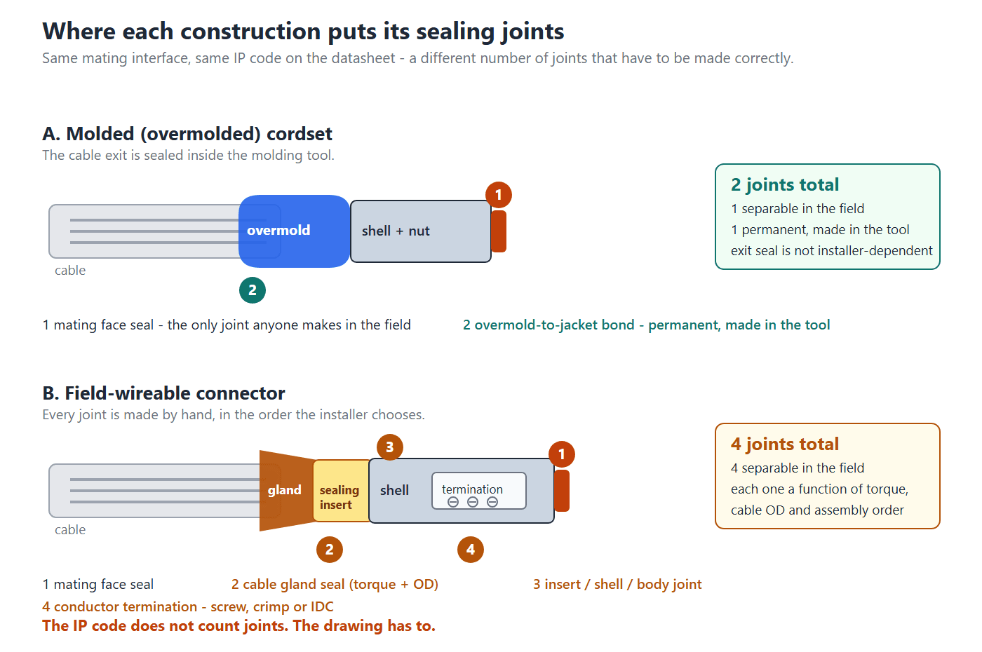
Figure 1 is the whole comparison in one drawing. A molded cordset has two joints: the mating face seal, and the overmold-to-jacket bond, which is permanent and was made in a tool. A field-wireable connector has four: the mating face seal, the cable gland seal, the insert/shell/body joint, and the conductor termination itself.
The point is not that four joints must fail. It is that variance enters the assembly at four places instead of one. Each separable joint depends on the right seal set, the right assembly order and the right torque; each one is a place where a substitute cable, a missing O-ring or a hurried installer changes the result. A molded cordset concentrates the same risk in one place — the molding process — which is a controlled, repeatable and 100 % testable process step.
When a datasheet says IP67 for both, it is describing the mating face, not the construction behind it. Section 3 explains what that actually certifies.
What the IP rating on the datasheet actually covers
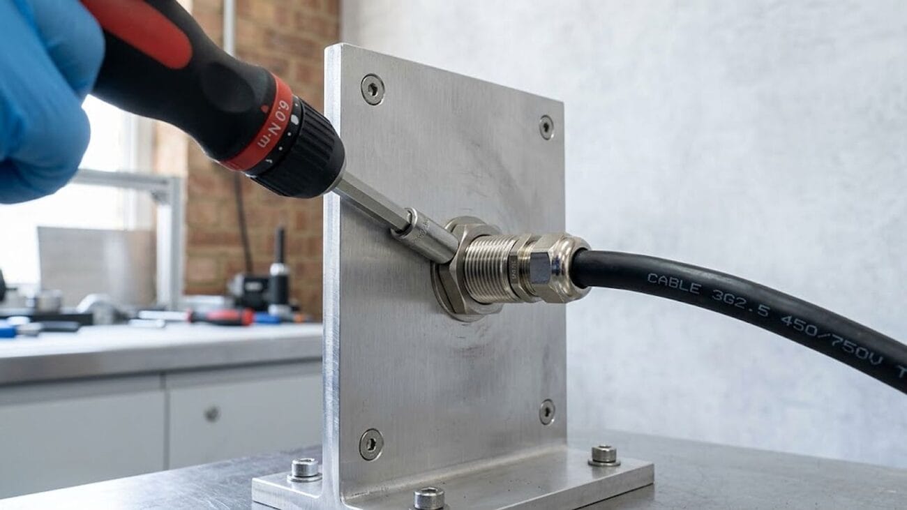
Ingress protection is defined in IEC 60529, and the standard tests a specimen that has been prepared according to the manufacturer’s instructions. The rating therefore belongs to a configuration: a specific cable outside diameter, a specific gland torque, a specific seal set, assembled by whoever built the test specimen. We have covered what the code does and does not mean in IP67 vs IP68 vs IP69K, and the same logic applies here.
For a molded cordset, the tested article and the shipped article are the same object, produced by the same process. For a field-wireable connector, the tested article was assembled by the connector maker’s technician; yours is assembled by yours. The rating transfers only if your assembly matches the tested one — same cable diameter, same seal set, same torque.
Cable glands are covered by EN 62444, which specifies cable retention, clamping and sealing requirements in addition to the ingress test. It is worth asking for those numbers, not just the IP code. And if the assembly will live outdoors, remember that water is only half the problem — thermal pumping, capillary wicking and UV are covered separately in waterproof cable assembly design for outdoor use.
Practical rule: ask the connector manufacturer which cable diameter and which gland torque the IP rating was achieved with, then put both numbers on your drawing. An IP67 rating with no diameter and no torque is a marketing statement.
The cable OD window: the number nobody checks
A field-wireable gland does not accept one cable diameter. It accepts a range, and the sealing insert has to work across the whole of it. The published table below is a real manufacturer’s reference set for plastic cable glands and shows how the recommended tightening torque changes with that range.
| Gland model | Cable OD range | Cap torque (N·m) | Lock-nut torque (N·m) |
|---|---|---|---|
| RM8S-2.5 | Ø1.0–2.5 mm | 0.6–0.7 | 0.4 |
| RM10S-6 | Ø3.0–6.0 mm | 0.5 | 0.5 |
| RM12S-7 | Ø3.5–7.0 mm | 1.2 | 0.6 |
| RM16S-8 | Ø4.0–8.0 mm | 1.6 | 0.7 |
| RM20S-12 | Ø6.0–12.0 mm | 2.0 | 1.8 |
The same catalog carries a warning worth copying onto your specification: waterproofing is also affected by cable diameter tolerance, jacket material hardness, ambient temperature and the tightening method, and the torque values are reference values only. That warning is the whole argument of this section in one sentence.
Now look at where a cable sits inside its window. Taking the RM12S-7 gland (a 3.5 mm span) as an example:
| Cable OD | Position in the 3.5–7.0 mm window | Window travel left | Verdict |
|---|---|---|---|
| Ø3.6 mm | 3 % | 97 % | Edge — insert barely closed |
| Ø4.0 mm | 14 % | 86 % | Edge |
| Ø4.8 mm | 37 % | 63 % | Good |
| Ø5.25 mm | 50 % | 50 % | Best |
| Ø6.0 mm | 71 % | 29 % | Acceptable |
| Ø6.6 mm | 89 % | 11 % | Edge — little travel left |
| Ø6.9 mm | 97 % | 3 % | Edge — avoid |
A cable that sits near either edge of the window leaves almost no travel for the things that vary in the field: jacket tolerance, jacket hardness at low temperature, and the torque the installer actually applied. Specifying the cable in the middle third of the gland window is the cheapest reliability improvement available on the field-wireable side.
A molded cordset has no such window to manage. The tool is cut for one cable diameter (or a narrow group), so the exit seal has exactly one geometry, and the coupling side carries the only torque in the assembly. How that coupling torque converts into seal load — and why a right-angle exit makes it worse — is the subject of waterproof connector torque and sealing load. On plastic M12 bodies the coupling thread is also easy to damage: published field guidance puts the useful range at about 0.4–0.6 N·m and notes that plastic threads strip above roughly 0.6 N·m (values that vary with thread form and housing material, so confirm the figure against your connector maker’s datasheet).
The termination is a different component
Behind the seals, the two constructions use different hardware to join copper to contact, and the difference shows up in vibration and in service.
Molded: contacts are crimped on a press with a calibrated applicator, then encapsulated. A crimp is a cold weld — the conductor strands and the contact barrel deform into a gas-tight joint, which is why crimp quality is specified and tested as its own process (IEC 60352-2 covers solderless crimped connections). Once molded, it cannot loosen, and it cannot be reworked.
Field-wireable: the three options trade consistency against rework.
- Screw-clamp is re-terminable with a screwdriver and tolerant of different conductor sizes, but the screw carries clamping force through a spring or a plain thread. Vibration and thermal cycling relax it, which is why re-torque appears on maintenance schedules, and why sine and random vibration testing (IEC 60068-2-6 and IEC 60068-2-64) matter for anything on a moving axis.
- Crimp-and-insert reaches molded-grade electrical quality but needs the correct crimp tool and dies in the field — and the joint is only as good as the tool that made it.
- IDC terminates without stripping and is very consistent if the conductor insulation falls inside the contact’s specified window; outside it, the blade either fails to pierce or cuts strands.
None of this makes field termination bad. It makes it a process with a human in it. That is also its advantage: a field-wireable joint can be opened, corrected and re-made, which is exactly what you want on a prototype and exactly what you do not want on a machine that ships in quantity.
Right-angle bodies, wrench access and the first bend
Both constructions are available with a 90° exit, but they are not the same part. A molded right-angle boot is a solid encapsulated body: the cable turns inside the boot, the strain relief is a continuous molded transition, and the outside is smooth. A right-angle field wireable connector has to house a termination block between the gland and the contact insert, so the body is longer and bulkier, and the cable leaves a straight gland before it turns — the turn happens in unsupported jacket, not inside the boot.
Two practical consequences follow. First, wrench access: a threaded coupling needs clearance for a tool on the flats, and a bulky right-angle body mounted close to a wall or a cabinet side takes that clearance away. Second, the first bend. A molded boot supports the cable for its whole length; a gland supports it for a few millimeters. The distance from the gland face to the point where the jacket can rest on something is what limits how hard the installer can pull the cable sideways.
The length of boot needed to complete a 90° turn at a given minimum bend radius is just a quarter-circle arc:
| Cable OD | At 4×OD (TIA-568 4-pair UTP) | At 8×OD (NEC 300.34, unshielded) |
|---|---|---|
| Ø4.5 mm | 28 mm | 57 mm |
| Ø5.5 mm | 35 mm | 69 mm |
| Ø6.5 mm | 41 mm | 82 mm |
| Ø7.5 mm | 47 mm | 94 mm |
Those are the distances over which nothing is supporting the cable on a field-terminated build. Whether a 90° exit is the right call at all — depth, side pull, service access and the rest — is a separate decision covered in right angle vs straight cable connector.
When a field wireable connector is the only thing that fits
Some installations are not a choice at all, and the deciding constraint is usually a hole. If a cable has to pass through a conduit, a bulkhead gland plate, a machine frame or a cabinet wall, the opening has to accept the largest cross-section of the assembled connector — coupling nut included, not the connector body. A molded cordset arrives assembled, so the hole always has to clear the finished part.
A field-wireable connector arrives as parts. The shell, the insert, the contacts, the seals and the coupling nut go through separately, and the assembly happens on the far side of the hole. That is the whole argument for field termination in retrofit work, in long conduit runs, and in anything where the harness is threaded before the equipment is in its final position.
The rule of thumb is not a dimension but a question: can the opening pass the largest single piece of the connector? If yes, a field-wireable build works. If the cable can be pulled after the panel is in place, a molded cordset works too, and it will be the better part.
Before you commit, price the work that the second option saves you:
- Terminating in place. The joint is made where the cable ends, which may be inside a cabinet, overhead, or on a machine frame. Every one of those is worse than a bench.
- Tool access at the coupling. A threaded coupling needs a wrench on the flats. Section 6 covers what a bulky right-angle body does to that clearance.
- No pre-test. A molded cordset is electrically tested before it ships. A field-terminated joint is tested by whatever process the installer follows, which usually means “plug it in and see”.
- Skill on the day. The quality of the joint tracks the skill and the working position of the person who made it. That variability is the reason Section 7 treats rework as a cost term rather than an accident.
None of this is an argument against field termination. It is the reason the decision belongs on the drawing with the routing, not in the purchasing system next to the part number.
The installed cost decides, not the part price
The part price says the field-wireable build is cheaper. It almost always is — bulk cable plus a connector kit costs less than a finished molded cordset. It is also the wrong number, because the field-wireable build buys a saving in parts by spending time and rework risk. Compare the two on installed cost per assembly:
Cinstalled = Cpart + tassembly × Rlabor + ffail × Cservice + Ctooling / N
where t is assembly minutes per unit, R is loaded labor cost per minute, f is the fraction of units that generate a service call, Cservice is the cost of one call, Ctooling is the one-time overmold tool, and N is the quantity over which it is amortized. Everything is a normal engineering input; the only term that separates the two constructions structurally is the last one.
Worked example, with illustrative inputs — replace them with your own quotes and your own field data:
| Input | Molded cordset | Field-wireable |
|---|---|---|
| Part price | $9.50 | $6.80 |
| Assembly time | 0.5 min (plug in, tighten) | 6.0 min (cut, strip, terminate, assemble, torque, test) |
| Field failure fraction | 0.2 % | 1.5 % |
| One-time overmold tool | $2,800 | — |
| Loaded labor / service call | $54 per hour ($0.90/min) / $180 per call | |
Fixed cost per unit is therefore $10.31 for the molded cordset (before tooling) and $14.90 for the field-wireable build — labor and expected rework cost the field-wireable build $8.10 per unit and give back only $2.70 on parts. The tooling term is what turns that around:
| Quantity | Molded cordset | Field-wireable | Cheaper build |
|---|---|---|---|
| 100 | $38.31 | $14.90 | Field-wireable |
| 200 | $24.31 | $14.90 | Field-wireable |
| 300 | $19.64 | $14.90 | Field-wireable |
| 500 | $15.91 | $14.90 | Field-wireable |
| 610 | $14.90 | $14.90 | Break-even |
| 1,000 | $13.11 | $14.90 | Molded |
| 2,000 | $11.71 | $14.90 | Molded |
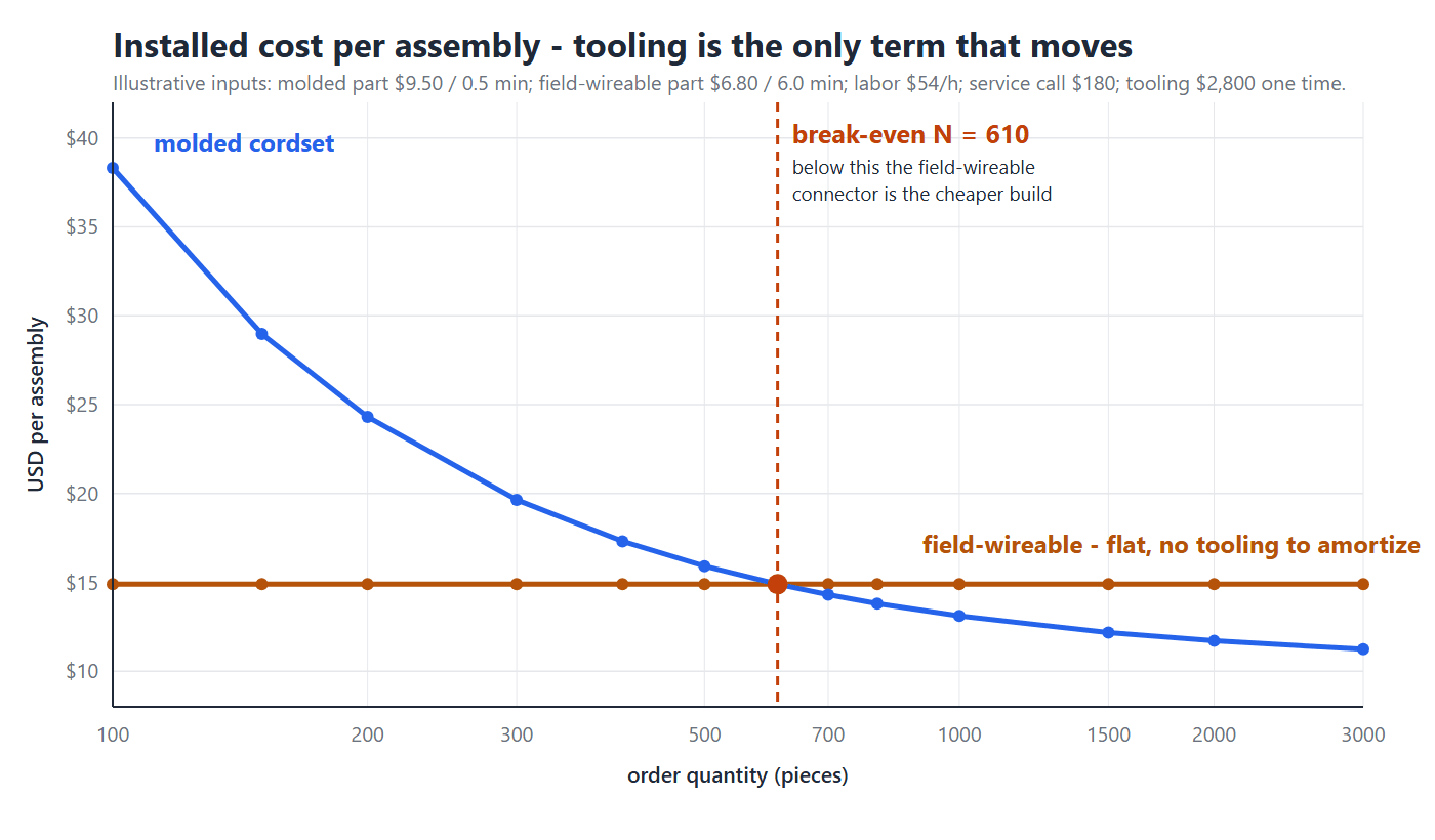
The same model says the answer depends on what your labor costs. Holding everything else fixed and varying the loaded rate:
| Loaded labor | Break-even quantity |
|---|---|
| $36/h | 952 pieces |
| $45/h | 744 pieces |
| $54/h | 610 pieces |
| $63/h | 517 pieces |
| $72/h | 449 pieces |
| $90/h | 355 pieces |
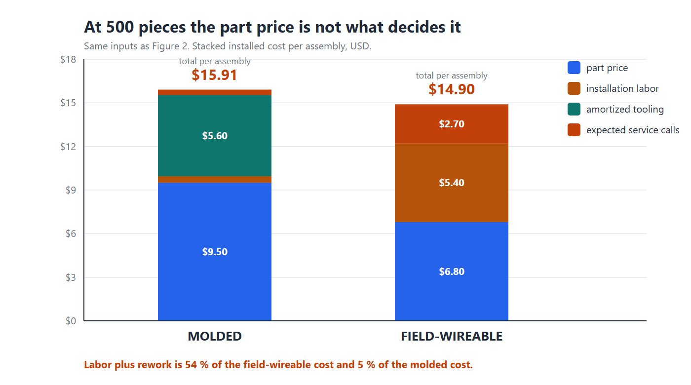
Read honestly, the model does not say “molded always wins.” It says the field-wireable connector is a low-volume tool and the molded cordset is a high-volume tool, and the boundary sits where your labor rate and your field failure history put it. It also explains normal practice without any argument: prototypes and one-off repairs are field-terminated because N is tiny and the length is unknown; production is molded because N is large and the length is known. At HKWIRE that split is how we quote — 500 pcs per part number for production, and 1 to 50 pcs for prototypes and samples — and it is why prototype builds are often delivered field-terminated while the production release moves to a molded tool.
Why most machines end up with both constructions
The comparison is usually framed as a choice, and on a real machine it rarely is. A single machine has sections with different constraints: some runs are fixed, repeated and exposed; others are one-off, measured on site and revised during commissioning. Specifying one construction for the whole machine means over- or under-engineering half of it.
The split that shows up again and again is trunk versus drop:
| Run | What is true of it | Construction that fits |
|---|---|---|
| Trunk / backbone | Fixed length, repeatable route, high volume, often outdoors or in a washdown zone | Molded cordset |
| Drop to a sensor or valve | Length set on site, route revised during commissioning, one or two pieces per machine | Field-wireable |
| Through a conduit or bulkhead | Opening is smaller than the assembled connector | Field-wireable |
| Panel feed-through | Mating face exposed, length fixed, sealing is critical | Molded cordset or a bulkhead receptacle |
| Spare / service loop | Length unknown until the machine is built | Field-wireable |
Notice what the table is really sorting on. It is not “which part is better” — it is whether the length is known before the cable is made. Where the length is known and repeated, a mold is worth building. Where it is not, the ability to cut and terminate on site is worth more than the consistency you give up.
The practical consequence for a drawing is simple: decide construction per run, not per machine, and write the decision into the callout so that the next revision does not silently change it. Section 8 lists the lines that belong on that callout.
What each construction does to your spare parts shelf
There is a cost that never appears on either quote, and it lands on whoever keeps the machine running: the number of distinct part numbers the choice creates.
A molded cordset is one part number per length. Ten lengths in the machine means ten stocked part numbers, each with its own lead time and its own minimum. A field-wireable build separates the two: one connector part number plus bulk cable by the metre covers every length on the machine. For a maintenance team, that is the difference between stocking ten items and stocking two.
| Molded cordset | Field-wireable | |
|---|---|---|
| Part numbers for 10 lengths | 10 finished assemblies | 1 connector + 1 cable |
| Spare held for a failure | The exact length, or a longer one coiled somewhere | One connector, cut to fit |
| What the technician needs | A screwdriver and the part | The part, a stripper, a terminator and the skill to use them |
| Time to restore a run | Swap and re-mate | Swap, strip, terminate, re-mate |
| Consistency of the repair | Same as the original | Depends on the technician |
| Ordering threshold | Production quantities, typically from 500 pieces | From a single piece |
Read the table in both directions. The field-wireable column wins on inventory and on the ability to fix something at 2 a.m. with what is on the shelf. The molded column wins on repair time and on the certainty that the replacement behaves exactly like the original. Which of those matters more depends on what a stopped machine costs you per hour, which is the same number that Section 7 asks you to put into the model.
This is also where the quantity question resolves itself. Prototype and pre-production work — the 1 to 50 piece range — carries no tooling, so a field-wireable build costs nothing extra to change. Once a run settles into production quantities, the tooling is amortized across it and the molded part is the cheaper one to own.
Inspection points and the ten lines for the drawing
Whichever construction you buy, the checks are cheap and the failures they catch are expensive.
On receipt of a molded cordset: continuity and insulation resistance on 100 % of units (the supplier should already have done this — ask), visual on the overmold for voids or exposed braid, and a pull check on the first article.
On completion of a field termination: all of the above plus the four joints from Figure 1 — gland torque against the published value, correct seal set for the actual cable diameter, insert fully seated, and coupling nut tightened to spec. A soap-water check on the mated face and the gland is crude but finds gross errors in seconds.
Ten lines that belong on the drawing for either construction:
- Mating interface and code (connector family, pin count, coding).
- Cable construction: conductor size, jacket material, OD and its tolerance.
- Construction: molded cordset or field-wireable, and who terminates it.
- Ingress rating, the standard it is tested to, and the mated condition it assumes.
- Cable OD the sealing system was qualified with.
- Coupling torque in N·m, and the thread material it applies to.
- Termination style and, for crimps, the tool and die.
- Exit direction and the minimum bend radius at the exit.
- Retention: pull-out force at the cable gland or overmold.
- Acceptance tests: continuity, insulation resistance, and the leak or pressure test if the rating demands one.
Most of this list is the same one we use for any custom build — how to specify an overmolded cable assembly covers the molding side in detail, and screw-lock molded cable assemblies and M8/M12 circular assemblies show the constructions discussed here as finished parts.
Frequently asked questions
Is a field wireable connector really IP67 like the datasheet says?
It can be. The rating was achieved with a specific cable diameter, seal set and gland torque, so your assembly has to reproduce that configuration. Ask for those two numbers and put them on your drawing; without them the code is a property of the manufacturer’s test specimen, not of your build.
Can a field-wireable connector be re-opened and re-used?
Usually yes, a limited number of times. The elastomeric seals and the termination are the wear items: replace the cable seal each time you re-enter, inspect the mating face seal, and re-terminate rather than re-use a crimped contact. Treat it as a serviceable joint with a budget, not a free one.
Why is a molded cordset more expensive per piece?
Because it carries a tool. The per-unit labor is near zero and the process is repeatable, but the tool has to be paid for. Above a few hundred pieces the tooling term falls below the labor and rework the field-wireable build carries, which is exactly what Figure 2 shows.
Which construction should I use for a prototype?
Field-wireable, almost always. Quantities are small, lengths are uncertain and the design will change. Just record the cable diameter and torque you used so that the production release can be qualified against the same configuration.
Does a screw-lock coupling change any of this?
No — the coupling is on the mating face and both constructions use the same one. What changes is clearance: a threaded coupling needs tool access to the flats, which matters more on a bulky right-angle field-wireable body than on a molded boot.
Is IDC termination reliable enough for the field?
Yes, within its window. Insulation-displacement contacts are designed for a specific insulation diameter and hardness range; inside that range they are fast and consistent, outside it they either fail to pierce or damage strands. Check the contact specification against your actual cable, not a similar one.
What single number should I check first on a field-wireable datasheet?
The cable OD range of the gland, and where your cable sits in it. A cable specified in the middle third of the window forgives torque and tolerance scatter; a cable at either edge does not.
Can I pull a molded cordset through the same hole as a field-wireable build?
Only if the opening clears the assembled connector, coupling nut included. A molded cordset cannot be taken apart, so the hole has to accept the finished part. If the opening is smaller, you either enlarge it or terminate on the far side — which is the argument for a field-wireable build. Check the largest cross-section of the assembled part before you commit to the route.
Should one machine use one construction throughout?
Rarely. Trunk runs have fixed lengths and repeat across machines, which is what a mold is for. Drops to sensors and valves are measured on site and revised during commissioning, which is what field termination is for. Decide per run rather than per machine, and record the decision on the drawing so a later revision does not change it by accident.
How many part numbers does each option put on my shelf?
A molded cordset is one part number per length, so ten lengths is ten stocked items. A field-wireable build is one connector part number plus bulk cable, which covers any length. The field-wireable option is far kinder to inventory; the molded option is kinder to repair time, because a spare is swapped rather than terminated.
HKWIRE — molded cordsets and field-terminated builds, quoted both ways. Send us the mating interface, the cable and the quantity, and we will show you the installed-cost crossover on your own numbers before you commit to a tool. Start at the RFQ page.