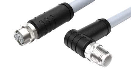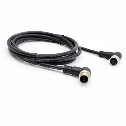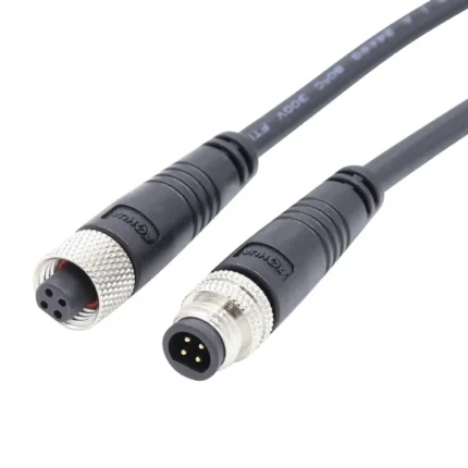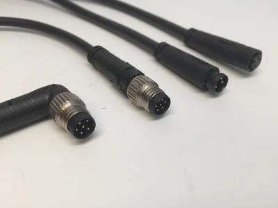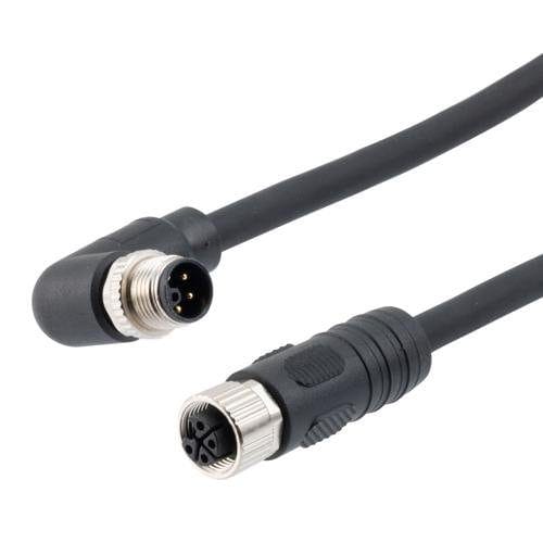
M12 L-Code Right-Angle Power Cable, 16 A / 63 V, IP67
This m12 l-code power cable angles the heaviest M12 power class out the back of the drive: the L-coded 4-plus-FE insert carries 16 A at 63 V, and the 90-degree exit sits flush where a straight coupling nut would not clear the cabinet wall.
Overview
This m12 l-code power cable angles the heaviest M12 power class out the back of the drive: the L-coded 4-plus-FE insert carries 16 A at 63 V, and the 90-degree exit sits flush where a straight coupling nut would not clear the cabinet wall.
L-coding is the 16 A workhorse of the M12 power family, and the right-angle body solves the geometry problem that comes with it: drive modules and compact power supplies often face their ports toward a wall or bracket, where a straight coupling nut cannot be gripped or routed. Angled exits keep the bend radius outside the connector instead of inside the cable.
Key Specifications
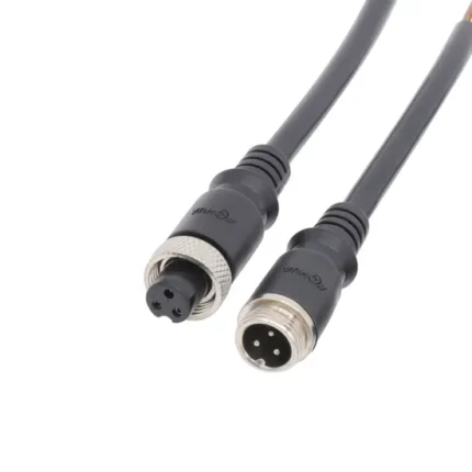
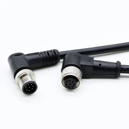
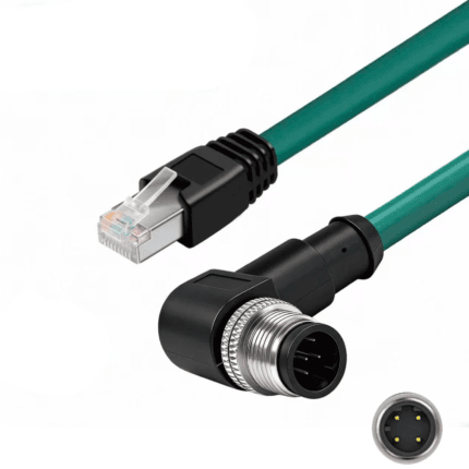
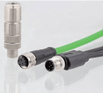
The table below lists the configuration shown in the product photo.
What L-Coding Is For
L-coding occupies the top of the DC side of the M12 power family. Standard coding references place it at 63 V DC and 16 A on a four-plus-FE contact layout, one step above the T-coded 12 A class and far away from the 630 V AC codings used for mains distribution. In practice that makes it the connector of choice for DC power delivery on PROFINET-based machines, where one coding is specified for every power port on the line so nothing is left to interpretation.
The reason it gets chosen over a larger connector is density. A 16 A feed in an M12 shell takes a fraction of the panel area that an equivalently rated industrial power connector occupies, and that saving is multiplied across every axis of a multi-drive cabinet.
What the FE Contact Actually Does
The fifth position in a 4+FE layout is the functional earth. It is not a spare pin and it must not be left floating. Its job is to make the protective earth connection first and break it last, ahead of the current-carrying contacts, so that a connector being mated or pulled under load never leaves a live conductor without its earth path.
Functionally it does two more things. It carries the fault current if a conductor shorts to the enclosure, giving the protection device a low-impedance route to trip on, and it ties the cable screen to earth at the right point, which matters a great deal on drive outputs where switching noise is present.
Why Right-Angle at the Drive
Equipment makers place their ports where the internals allow, which frequently means facing a wall, a bracket or another connector. A straight power cordset plugged into such a port then has to turn ninety degrees immediately, and a power-sized cable does not do that politely: it needs bend radius, and that radius plus the straight connector body often exceeds the clearance the enclosure actually has.
Moving the turn inside the connector changes the arithmetic. The cable leaves parallel to the mounting face, the installed depth above the panel drops to roughly the body height, and anything swinging past that face — a cabinet door, a robot link, a cable tray cover — has a much flatter profile to clear.
Construction and Materials
The overmolded body turns the cable ninety degrees from the coupling axis while the potting seals the full contact cavity, so ingress protection does not depend on the exit direction. The knurled nut still tightens with a standard grip even in the shallow clearance behind the device, and the power conductors are sized for the 16 A class.
The right-angle body is molded in one shot with the potting carried around the bend, so the seal path does not change at the ninety-degree exit. Conductors are sized for the 16 A class, and the nut knurl is deep enough to grip in the shallow clearance behind a drive.
Typical Applications
Fit it to servo drive power ports recessed in cabinets, robot base power connections where the socket faces the pedestal, busbar tap-offs on conveyor drives, and any L-coded port mounted close to a surface.
Conveyor and material handling lines use it where the drive sits against a frame member. Mounting the drive flat against the structure saves panel area, and the only way to wire such a port is with an exit that runs along the frame rather than into it.
Robot bases and pedestals are similar: the power inlet typically points down or back, and the dress-out has a defined path it must follow. A straight connector would push the cable into that path.
Recessed power supplies in compact control cabinets round out the list, particularly on machines where the cabinet depth was dictated by something other than the cabling.
Compatibility and Fitment
The keyway follows the L-coding used across standard M12 power ports and mates with L-coded receptacles regardless of manufacturer; it cannot mate with A, D or T-coded connectors. Confirm your port is L-coded before ordering.
Note also that this family is gradually replacing larger 7/8-inch power connectors in new designs, offering comparable current in a much smaller footprint. If you are retrofitting older equipment that was wired with 7/8-inch devices, check the port before assuming a size.
Decide the Exit Direction at Order Time
A right-angle body is molded in one orientation relative to the keyway, so the cable leaves in one direction only. That direction matters: on a cabinet wall it determines whether the cable runs up, down, left or right once the plug is seated.
The mistake is easy to make and expensive to fix, because a wrongly clocked exit usually cannot be corrected without a new build. Tell us which way the run has to go, or send a sketch of the port with the panel edges marked, and we will set the orientation to match.
Installation and Strain Relief
Support the cable close to the connector. Sixteen amp conductors are heavy, and letting that weight hang off a ninety-degree body puts sustained leverage exactly where the jacket enters the molding.
Tighten the nut by hand to a firm seat, not with pliers. Crushing beyond the designed seal compression does not improve the joint and can distort the very seal the rating depends on.
Custom Builds and Ordering
Lengths, exit direction and conductor sizes are built to order. Send the drive model and panel drawing and we will quote the matching assembly. Prototype and sample lots run from 1 to 50 pieces and ship in 3 working days; production orders start at 500 pieces per part number and ship 14 working days after approval, with new overmold tooling adding about 10 working days.
Packaging and Shipping
Bagged with a dust cap over the mating face; bulk packs with OEM labels are available.
Quality and Compliance
Continuity across all contacts, including the FE path, plus seal checks are completed on every unit before shipment. See the IEC M12 power connector standards for the governing interface specification.
Material declarations against RoHS and REACH are issued per project, alongside the dimensional and electrical reports agreed at quotation; see certifications, compliance and material declarations. Where your drawing names a UL style or another approval, the build follows your drawing and ships with the supporting document rather than a claim of our own. Exit direction is a tooling decision, not a field bend see right-angle overmold tooling options for the forms we mold and when each one makes sense. Related reading: what automation programs ask for. Tooling for this build is cut in our own tool room and belongs to your program, so a repeat run years later starts from the same tool.
Frequently Asked Questions
Will it mate with a T-coded port? No. The keyways are different and deliberately so.
Can the exit direction be changed later? No. Orientation is set when the body is molded, so specify it with the order.
Does the FE contact have to be connected? Yes. It is the protective earth path and should never be left floating.
Is this a straight replacement for 7/8-inch power connectors? Electrically comparable in its class and much smaller, but confirm the port style on existing equipment before ordering.
Related Cable Ranges
Browse the related ranges: Circular M-Series Cable Assemblies Screw-Lock Molded Cable Signal and Data Cables.
For the step below this in current see the M12 T-code power cable, and for heavier hybrid motor feeds the IP67 right-angle M23 power cable.
| Coding | L-coded, 4 plus FE contacts |
|---|---|
| Rating | 16 A / 63 V |
| Orientation | 90-degree right angle |
| Ingress Rating | IP67 when mated |
| Application | Drive power, compact cabinets, robot bases |
| Coupling | M12 threaded, knurled nut |