

An overmolded cable assembly is one where the strain relief and connector boot are molded as a single soft polymer body around the cable and contacts, not a separate molded plastic shell snapped over a crimp. That one-piece boot is why overmolded cordsets outlast field-wireable connectors in pull, flex and washdown. But “overmolded” is not a single specification: the material, the boot geometry, the IP rating and the tooling all change the result. This guide is about what to put in the purchase order so the part you receive matches the duty you need — including the torque figure that decides whether the seal works, and the retention figure that decides whether the cable stays attached.
Our take is practical: HKWIRE runs more than 100 in-house mold tools, so the boot is designed around your cable and panel rather than forced into a catalog shape. See also what engineers should define in an overmolded design for the drawing side of the same problem.
1. Choose the overmold material
The overmold is both the seal and the handle, so it has to survive the chemistry, the temperature and the number of mating cycles. The temperature figures below are nominal service ranges of the kind published in material guides and cable-maker tables, not limits taken from a connector standard:
| Material | Use when | Watch out for | Nominal temperature range |
|---|---|---|---|
| TPE (thermoplastic elastomer) | Halogen-free, wide temperature, good flex, matte grip | Softer grades can tear at a sharp panel edge | −50 to 105 °C |
| PVC overmold | Low cost, indoor, light duty | Stiffens in the cold; not an oil-resistant choice | −20 to 105 °C |
| TPU / PUR | Abrasion, oil, repeated flex, washdown | Harder feel; sustained heat above about 80 °C | −55 to 80 °C |
| TPE plus nylon collar | High pull strength at the boot | The nylon insert carries the strain, so it must be anchored inside the body | Set by the TPE compound |
| LSR (liquid silicone rubber) | Wide temperature and aggressive chemistry | Higher cost; bonding to some jackets needs a primer | Roughly −50 to 200 °C |
If the cable will see oil, coolant or continuous flex, ask for TPE or TPU, not PVC. The decision that actually bites is the temperature one: a PUR boot is the toughest general-purpose choice and also the one with the lowest ceiling, so an assembly that sits near a motor housing needs the material chosen against the measured surface temperature, not the ambient in the cell.
The torque spec on an overmolded cable assembly: from N·m to clamp force
Almost every overmolded assembly ends in a threaded coupling — a screw-lock coupling nut, a panel jam nut, a cable gland — and the purchase order almost always states a torque. Almost nobody states what that torque is supposed to achieve. It is worth converting it once, because the conversion exposes a problem that no general sealing article mentions.
The short-form torque relationship used across fastener engineering is T = K · D · F, where T is the tightening torque in N·m, D is the nominal thread diameter in meters, K is the dimensionless nut factor that bundles thread friction and under-head friction, and F is the resulting axial clamp force in newtons. Rearranged, the number you actually care about is:
F_clamp = T / ( K × D )
The nut factor is not a clean physical constant — it is an empirical term that absorbs the thread condition, the under-head friction and any plating or coating. VDI 2230, the German guideline that is the primary reference for systematic bolted-joint calculation, expresses the same relationship in its extended form as the sum of a thread-lead term, a thread-friction term and an under-head friction term, with the nut factors published as ranges rather than single values. The practical consequence is shown below for the most common industrial thread, M12:
| Tightening torque | Clamp force at K = 0.20 (dry, as-received) | Clamp force at K = 0.14 (lightly oiled or coated) |
|---|---|---|
| 0.5 N·m | 208 N | 298 N |
| 1.0 N·m | 417 N | 595 N |
| 1.5 N·m | 625 N | 893 N |
| 2.0 N·m | 833 N | 1,190 N |
| 2.5 N·m | 1,042 N | 1,488 N |
| 3.0 N·m | 1,250 N | 1,786 N |
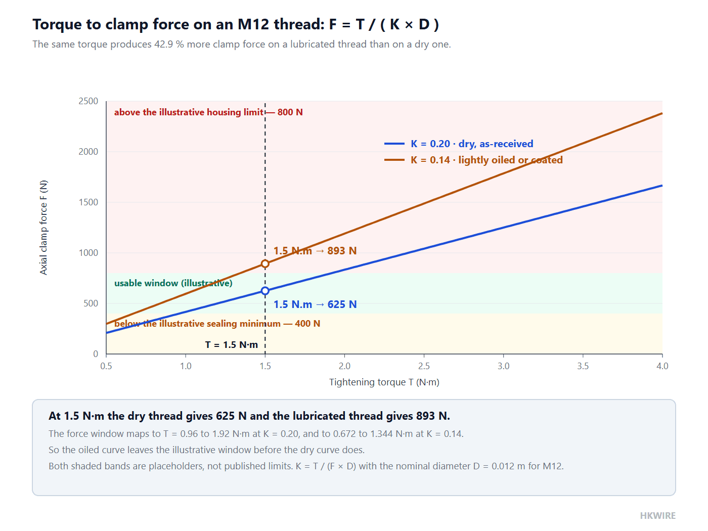
The table is the argument. At a stated 1.5 N·m, an overmolded cable assembly produces 625 N of axial clamp force if the threads are dry as received, and 893 N if a light oil or a coating has reduced the friction — a 42.9% difference in load for the identical torque number. Both assemblies pass the same incoming inspection with the same torque wrench. One of them is compressing its seal 43% harder than the other.
The same effect works in the other direction on thread size, and this is the part that catches people out when they copy a torque value between product families:
| Thread | Nominal diameter used in the formula | Clamp force at 1.5 N·m with K = 0.20 |
|---|---|---|
| M8 | 0.008 m | 938 N |
| M10 | 0.010 m | 750 N |
| M12 | 0.012 m | 625 N |
| M16 | 0.016 m | 469 N |
| M20 | 0.020 m | 375 N |
Copying “1.5 N·m” from an M16 product onto an M8 product multiplies the clamp force by 2.5. On a molded polymer housing, that is how a specification turns into a cracked flange.
Why the torque window matters more than the torque number
Put the two limits together. The lower limit is set by the seal: an O-ring face seal needs a specific squeeze to seal at all. The upper limit is set by the housing: a molded polymer body crushes, creeps or cracks above some clamp load. Between them is the working window. Solve T = K · D · F for both ends and the window follows:
| Nut factor | Torque to reach an illustrative 400 N sealing minimum | Torque at an illustrative 800 N housing limit | Usable window |
|---|---|---|---|
| K = 0.20 (dry) | 0.96 N·m | 1.92 N·m | 0.96 N·m wide |
| K = 0.14 (oiled or coated) | 0.672 N·m | 1.344 N·m | 0.672 N·m wide |
The two force values above are illustrative placeholders, not published limits. They are there to show the shape of the problem, and in a real specification both must come from the connector maker’s data: the minimum sealing force from the seal design, and the maximum from the housing material and wall thickness. The point that survives regardless of the numbers is that the same physical window of force maps to two different windows of torque, depending on a friction coefficient that is not written on the connector. Which is why the correct instruction on a drawing is not “tighten to 1.5 N·m” but “tighten to 1.5 N·m in a dry, unlubricated thread; do not apply anti-seize”.
For reference, the nut factors that appear in fastener references vary more than the thread dimensions do: as-received steel is commonly taken as 0.20, zinc-plated as roughly 0.17 to 0.22, lightly oiled as 0.13 to 0.17, molybdenum-disulfide lubricant as 0.10 to 0.12, and PTFE or wax coatings as low as 0.08 to 0.10. A summary of the VDI 2230 relationships and the corresponding nut factor ranges is available at this bolted-joints engineering reference. Always confirm the torque with the connector maker, and where the joint is critical, with a test to ISO 16047.
2. Define the strain relief, not just “with boot”
The whole point of overmolding is to kill the stress concentration at the cable entry. An overmolded cable assembly that is sold as “with boot” tells you nothing, because a boot can be a cosmetic sleeve or a structural transition. Specify:
- Boot length and taper — a longer transition gives a gentler bend, but only if the taper starts at the connector body. A long boot that is straight for its first half does nothing.
- Bend direction — straight, 45 degrees or 90 degrees, matched to how the cable must leave the panel rather than to what is in stock.
- Strain member — a bonded nylon layer, aramid yarn or a molded-in collar that carries the pull-out load so the conductors and the crimp do not.
- Hardness (Shore A) — softer compounds grip and seal better, harder ones resist abrasion and extrusion. The value must come from the compound data sheet; there is no universal correct number.
Retention is where a specification either becomes verifiable or stays decorative, and for industrial cordsets there is a real standard to point at. UL 2238 is the standard written specifically for cable assemblies and fittings for industrial control and signal distribution — the first standard of its kind for these products rather than an interpretation of UL 508 or UL 1977. Its §24 strain-relief test is a one-minute straight pull applied between the fitting and the cord, and the pass criterion is not only that the assembly holds together: the force must not be transmitted to the terminals.
| UL 2238 requirement | Test | Requirement for 18 AWG (0.82 mm²) and larger conductors |
|---|---|---|
| §24 Strain-relief test | Straight pull, 1 minute, between fitting and cord; force must not reach the terminals | 30 lbf = 133 N |
| Table 24.1, smallest conductors | Same test, stepped down by conductor size | 2 lbf = 8.9 N |
So the phrase to write is not “good strain relief”. It is “held to ≥133 N per UL 2238 §24 with the conductors fully inside the molded body”. That is a number a supplier can be measured against, and the scope of the standard that contains it is set out on the UL 2238 product page.
A common specification says “pull-out ≥150 N” for a sensor cordset. That number is not from a standard — it is a vendor’s margin above the UL 2238 floor of 133 N. Quoting 150 N is not wrong, but quoting it as “the standard requirement” is, and it becomes a problem the moment a supplier ships an assembly built to the standard rather than to your margin.
Bond or interlock: how the overmold actually grips
Injection-molding a polymer over a smooth cylindrical cable jacket produces an assembly held together by adhesion alone. That works, and it is what most overmolded cable assemblies rely on, but it is sensitive to jacket formulation, to surface contamination and to the mold temperature cycle. On a demanding overmolded cable assembly, mechanical interlock is the more robust alternative, and it is why the best designs have geometry rather than only chemistry:
- Knurling or a stepped surface on the ferrule gives the polymer something to key into, so pull-out load is carried in shear across many small features rather than in tension across one bond line.
- Through-holes or slots in an internal metal body let the overmold flow through and form mechanical pins.
- A shoulder or a step in the cable entry means the polymer does not have to resist the pulling force on a bond line at all, but in compression against a face.
This is exactly the kind of thing that belongs in a design-for-manufacture review rather than a purchase order, which is the argument for involving the molder before the housing geometry is frozen. Once the tool exists, the interlock geometry is fixed; changing it means a new tool.
Retention force and bend transition are two different specifications
These get merged constantly, and merging them is why failed assemblies come back with the wrong corrective action applied. They are separate requirements with separate failure modes and separate tests:
| Requirement | What it protects against | How it is expressed | How it is verified |
|---|---|---|---|
| Retention (pull-out) | The cable being pulled out of the molded body, or the load reaching the crimp | Newtons, for example ≥133 N to UL 2238 §24 | Straight-pull test, one minute, cord against fitting |
| Bend transition | Jacket cracking and conductor fatigue where the cable leaves the boot | A radius gradient — the smallest bend radius the boot must allow, and over what length | Flex or bend-cycle test on the assembled cord, and a physical check of the boot taper |
An overmolded cable assembly can pass the pull test and still crack its jacket in a flexing application, because the pull test says nothing about the boot’s exit geometry. The reverse also happens: a boot with a beautiful long taper but no internal strain member will pass every bend test on the bench and then pull apart at 200 N in the field. Ask for both numbers, and for the mold drawing that shows the taper.
3. Set the ingress protection (IP)
Washdown and outdoor duty need a sealed boot, and the rating comes from two seals rather than one. The cable-to-boot seal is created where the polymer bonds to, or mechanically grips, the jacket. The connector-to-panel or connector-to-mating-face seal is the O-ring or gasket. Both must work, and neither is guaranteed by the other. The IP code itself is defined by IEC 60529, in which the first characteristic numeral rates protection against solid objects and dust on a scale from 0 to 6, and the second rates protection against water from 0 to 9:
| Rating | Solids | Water test and conditions |
|---|---|---|
| IP67 | 6 = dust-tight | Temporary immersion. The lowest point of the enclosure is at least 1 m below the surface and the highest at least 150 mm below it, for 30 minutes (IEC 60529) |
| IP68 | 6 = dust-tight | Continuous immersion beyond 1 m. Depth and duration are agreed between manufacturer and user and must be more severe than the IPX7 test — the code alone states nothing (IEC 60529) |
| IP69K | 6 = dust-tight | Close-range high-pressure hot-water jet: water at 80 °C, 80 to 100 bar, nozzle 100 to 150 mm from the surface, 14 to 16 L/min. Defined in ISO 20653; the 9K notation came from DIN 40050-9 |
The free IEC preview of the standard is worth reading before you write an IP requirement into a drawing, because it makes two things explicit: an X in a code position means the test was not performed or not declared, not that protection is zero, and the water numerals are not a single ladder. Jet tests (5 and 6) and immersion tests (7 and 8) are different physical tests, so an assembly rated for immersion has not necessarily passed a jet test and vice versa. The full text is available from the IEC 60529 preview document.
Do not claim IP69K unless both seals and the connector rating support it. A soft seal that holds perfectly under the static pressure of 1 m of water can be torn apart by a 100 bar jet, and a rigid seal built for the jet can leak under slow immersion. Our screw-lock molded cordsets are built for IP67 duty; tell us if the application needs IP69K.
IP is a result, not a material: specify the cable OD window
The most common cause of a water-ingress claim on an overmolded cable assembly is not a bad connector. It is a correct connector fitted to a cable whose outer diameter is outside the range the seal was designed for. An O-ring or a radial seal is a designed interference fit: it seals when its cross-section is compressed within a specific band. The seal designer chose the band for a particular range of cable and housing diameters, so the rating belongs to that combination, not to the part number.
Squeeze is the quantity that matters, and it is expressed as a percentage of the free cross-section diameter. The published design charts give the bands:
| Seal design parameter | Published value | Source |
|---|---|---|
| Squeeze, static face seal, 1.78 mm (0.070 in) cross-section | 19% to 32% | Parker O-Ring Handbook ORD 5700, Design Chart 4-3 |
| Squeeze, static face seal, 2.62 mm (0.103 in) cross-section | 20% to 30% | Parker O-Ring Handbook ORD 5700, Design Chart 4-3 |
| Squeeze, static face seal, 3.53 mm (0.139 in) cross-section | 20% to 30% | Parker O-Ring Handbook ORD 5700, Design Chart 4-3 |
| Squeeze, static face seal, 5.33 mm (0.210 in) cross-section | 21% to 30% | Parker O-Ring Handbook ORD 5700, Design Chart 4-3 |
| Recommended maximum compression, static seal | 40% | Generic O-ring design guidelines |
| Recommended maximum compression, dynamic seal | 30% | Generic O-ring design guidelines |
| Recommended stretch of the ring over the groove | 1% to 5%, with 2% preferred | Generic O-ring design guidelines |
| Groove width | Approximately 1.5 × the O-ring cross-section | Generic O-ring design guidelines |
Read the first four rows as a single statement: the correct squeeze is a band, roughly 20% to 30% for a static face seal, and anything outside it either fails to seal or takes a permanent set. The generic design guidelines behind the last four rows are set out in full at this O-ring design guideline reference. Now apply that to a connector specification. If the seal is designed to give 20% to 30% squeeze on a jacket of 6.0 to 6.5 mm, then a 7.0 mm jacket produces more squeeze than the design allows — harder assembly, faster compression set — and a 5.5 mm jacket produces less than 20%, which is a leak waiting for the first washdown.
This is why an overmolded cable assembly specification must read “rated IP67 when assembled with a cable of 6.0 to 6.5 mm outer diameter”, and not simply “IP67”. The rating is a function of the implementation. Write the outer-diameter window next to the IP code, and require the supplier to state the window on the drawing.
4. Locking style for the environment
The boot does not keep the connector seated. That is the lock’s job, and the lock is the part that decides whether a vibrating machine sees a momentary open circuit:
| Lock | Best for | Mechanism |
|---|---|---|
| Screw-lock | Vibration, mobile equipment, washdown | A threaded coupling nut draws the two halves together and holds them under preload |
| Bayonet | Fast mate, moderate vibration | A quarter-turn engagement with a spring-detented ramp |
| Push-pull | Frequent connect and disconnect, low vibration | Axial detent; fast, but no preload to resist vibration |
| Latch | Cost-sensitive, largely static duty | A molded plastic catch; the least resistant to repeated side load |
For vibrating or moving equipment, screw-lock is the safe default, because it is the only one of the four that generates a sustained preload rather than relying on a detent. That is also why the torque calculation earlier in this article applies to it: the screw-lock coupling is a threaded joint, and its clamp force follows the same equation. This is exactly the comparison we wrote up in the screw-lock versus latch comparison.
5. Tooling and MOQ
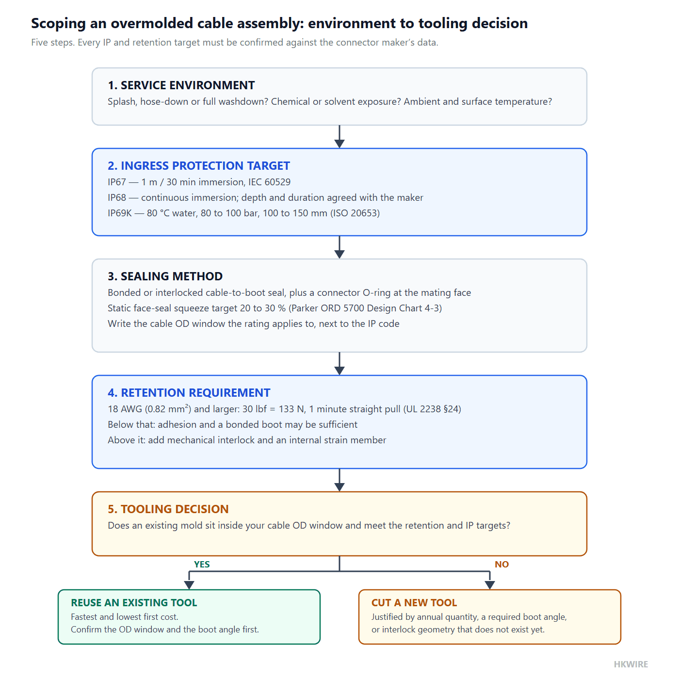
Because the boot is a molded part, the first overmolded cable assembly carries a tooling cost and a lead time, after which repeats are cheap. That makes the tooling question a decision, not a price: the right question is whether the volume justifies a dedicated tool, or whether an existing tool plus a cable change gets you close enough. The decision turns on four inputs, all of which are knowable before you ask for a quote.
| Input | Points toward an existing or shared tool | Points toward a new dedicated tool |
|---|---|---|
| Annual quantity | Prototype and small production runs | Repeat production where the amortized tooling cost per part becomes small |
| Boot angle and panel interface | The cable can leave at an angle an existing tool already supports | The panel geometry forces a specific angle that no existing tool has |
| Cable outer diameter and jacket | Within the outer-diameter window of an existing tool, and the jacket bonds reliably | Outside the window, or a jacket the compound will not bond to |
| Retention and sealing requirement | A standard geometry already meets the pull and IP requirement | UL 2238 retention or a specific IP target needs interlock geometry that does not exist |
Clarify three things up front. Tool ownership: does the mold belong to you or is it shared, and what happens to it if you move the product? Color and marking: boot color, laser etch or mold mark, which is how traceability gets onto a molded part at all. First-article approval: what sample quantity you get, and what you test it against — the pull figure and the IP window, presumably, not a visual check.
What to put on the RFQ
To get a usable quote, send the cable specification (conductors, outer diameter, jacket compound), the flex, abrasion and chemical exposure, the required IP rating together with the cable outer-diameter window it applies to, the lock type, the boot angle, the retention figure and the annual quantity. Our custom cable assembly RFQ checklist lists every field, and the jacket chemistry question is covered in more depth in our guide to halogen-free, oil-resistant and UV-stable cable jackets.
How we help
Send HKWIRE the cable specification and the duty, and we will tell you which existing tool is closest, what the boot geometry does to your bend radius, and which retention and IP figures the assembly can actually be held to. If a new tool is the right answer we will say so; if a catalog boot plus your cable will do, we will say that too.
Frequently asked questions
Overmolded versus field-wireable — which lasts longer?
Overmolded, in pull, flex and washdown duty. The boot removes the stress concentration at the cable entry and seals it, and it carries the pull-out load internally. Field-wireable connectors rely on a separate strain relief that loosens over time.
Is PVC overmold acceptable for industrial use?
Only for light indoor duty. For oil, abrasion or continuous flex, specify TPE or TPU. Check the nominal service temperature of the compound against the measured surface temperature of your enclosure, not the ambient in the cell.
Can you match an existing connector shape?
Often, yes. With more than 100 mold tools on hand, many boots need no new tool at all. If none fits, a new tool is quoted with its lead time, and the decision is whether the annual quantity justifies it.
What IP rating can an overmolded cable assembly reach?
IP67 is routine with a sealed boot and a correct O-ring, and IP69K is reachable when the connector rating and both seals support it. What matters more is that the rating is stated against a cable outer-diameter window, because the seal is a designed interference fit and a different jacket diameter moves it out of band.
Why does the same torque give a different clamp force?
Because the nut factor K is not constant. At 1.5 N·m on an M12 thread, a dry as-received thread produces about 625 N of clamp force while a lightly oiled or coated thread produces about 893 N — a 42.9% difference for the same torque reading. State the thread condition on the drawing, or the torque figure does not define the load.
What pull-out force should an overmolded cordset hold?
For industrial control cordsets the reference is UL 2238 §24, which requires 30 lbf (133 N) for 18 AWG and larger conductors, applied as a one-minute straight pull between fitting and cord, with no load reaching the terminals. A supplier may offer margin above that, but that is the floor.
Does a longer boot always mean a gentler bend?
No. Length only helps if the taper starts at the connector body and continues to the jacket. A long boot with a straight first half moves the stress concentration without reducing it. Ask for the mold drawing that shows the taper, not the boot length alone.
What is the difference between a strain relief and a bend relief?
They are two specifications. Retention force resists the cable being pulled out and is measured in newtons with a straight pull test. Bend transition controls the radius gradient where the cable leaves the boot and is verified with a flex or bend-cycle test. An assembly can pass either and fail the other.







