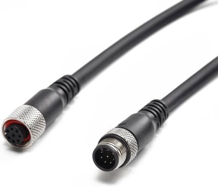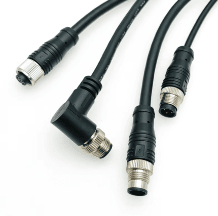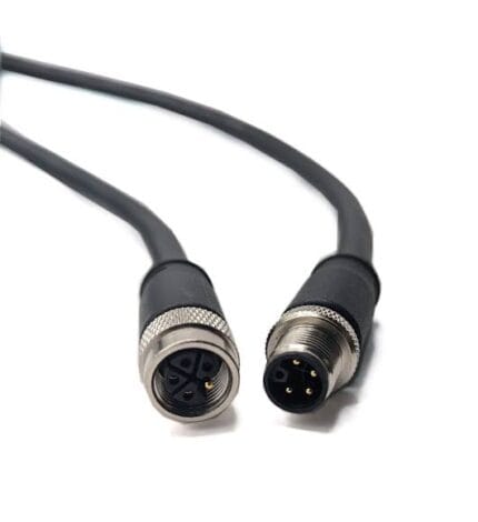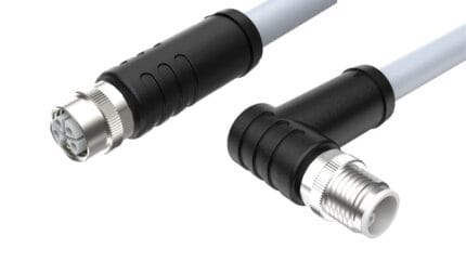
M12 Y-Coded Hybrid Cable for Power and Fast Ethernet
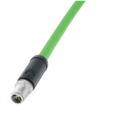
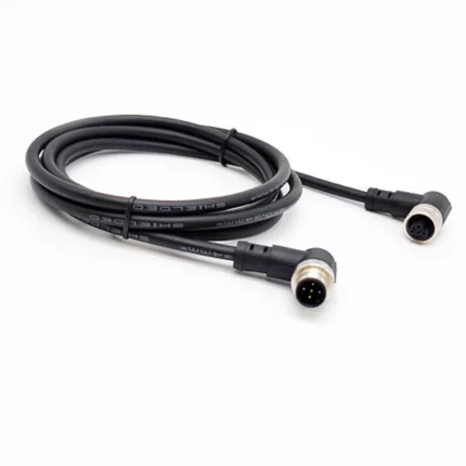
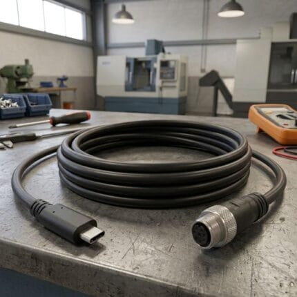
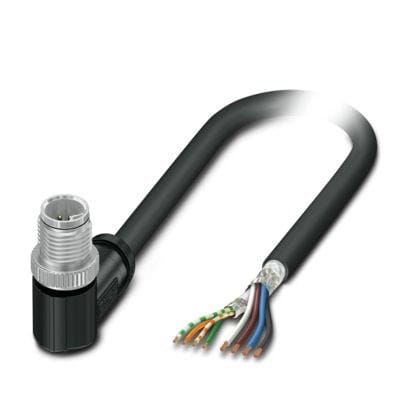
An M12 Y-coded hybrid cable puts four power conductors and two 100 ohm Ethernet pairs in one 8-position shell, so a cobot joint or AMR cluster needs one cable instead of two. Built to the pinout, jacket and length on your drawing.
Overview
A M12 Y-coded hybrid cable carries power conductors and a Fast Ethernet link inside one M12 shell. The argument for it is arithmetic rather than elegance: on a collaborative robot joint, a conveyor module or an AMR sensor cluster, a second cable costs a second connector, a second routing path and a second part number. Eight positions are available, four used for power and four for the data pairs.
Key Specifications
| Connector series | M12, Y-coded, 8 positions (4 power + 4 data) |
|---|---|
| Interface standard | Hybrid M12 interface per IEC 61076-2-113 (confirm applicable edition) |
| Power conductors | 4 x 0.85 mm2 class (pending supplier datasheet) |
| Data conductors | 4 x 0.15 mm2 class, 100 ohm nominal (pending supplier datasheet) |
| Voltage rating | 48 V AC / 50 V DC class (pending supplier datasheet) |
| Current rating | 6 A class (pending supplier datasheet and derating curve) |
| Data performance | Cat5 class, 100 Mbps (pending channel test) |
| Characteristic impedance | 100 ohm ±5 percent (pending supplier datasheet) |
| Jacket material | Halogen-free PUR, black |
| Outer diameter | 8.8 mm class (pending supplier datasheet) |
| Versions | Straight / right-angle, push-pull option |
| Typical loads | Cobot joints, conveyor modules, AMR sensor clusters, vision nodes |
Why Y-coding exists
Once a machine carries power and data on the same connector family, the risk is cross-mating. Y-coding is keyed so a hybrid plug will not enter an A-coded sensor receptacle, a D-coded PROFINET outlet or an X-coded 10 gigabit port, which protects the data equipment from meeting a power source. The hybrid M12 interface is described in IEC 61076-2-113; confirm the applicable edition before you standardize on it.
Y keeps a hybrid plug out of every other M12 receptacle on the machine, which is the whole point of it. The download center carries a coding reference covering A through Y with pole counts, duties, and which combinations will not mate.
The Y-code 8-position layout
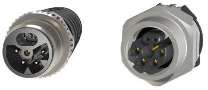
Think of the face as two zones rather than eight pins. Four positions sit in the power zone and four in the data zone, and the two zones are separated inside the shell so the power conductors do not run alongside the pairs.
| Zone | Positions | Function | Design note |
|---|---|---|---|
| Power zone | 4 positions | Supply and return for the load | Sized by current and routed length, not by pin count |
| Data zone | 4 positions | Two 100 ohm Ethernet pairs | Pair twist maintained to the termination |
| Screen | Shell and braid | Common reference for the data zone | Bonded all around, not pigtailed |
| Keyway | Shell profile | Blocks mating with A, D and X receptacles | Check the receptacle on site before ordering |
Which pin number lands on which function is exactly the kind of detail that differs between suppliers in a young interface. Send us the pinout of both ends and we will build to it rather than to an assumption.
Sizing the power conductors
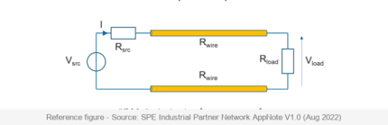
Most hybrid installations run at extra-low voltage, typically 48 V AC or 50 V DC class, where the current rather than the insulation limits the design. Four power conductors at 0.85 mm2 class are quoted in competitor data, but voltage drop decides whether a joint at the end of a robot arm sees its supply at all: at 6 A over ten meters the drop is significant, and on a moving arm the routed cable is longer than the straight-line distance suggests. Send us the load current and the routed length and we will check the drop before we quote a cross-section.
The M12 coding family, seen from a hybrid build
If the machine already carries a mix of codings, the hybrid is one more keyway to keep track of. This is the family as it is usually laid out on a spec sheet.
| Coding | Positions | Signal type | Voltage class | Typical home |
|---|---|---|---|---|
| A | 3 to 12 | Sensor and actuator signals | 30-250 V | Proximity switches, IO-Link |
| B | 4 to 5 | PROFIBUS-DP | 60 V | Older fieldbus installations |
| C | 3 to 6 | AC power | 250 V AC | AC sensors, being displaced by S |
| D | 4 | 100 Mbit/s Ethernet | 60 V | PROFINET and EtherNet/IP drops |
| X | 8 | 10 Gbit/s Ethernet | 60 V DC | Vision, Cat6A runs |
| S | 2+PE / 3+PE | Single-phase AC power | 630 V AC | Mains distribution |
| K | 4+PE | Three-phase AC power | 630 V AC | Motor feeds, drives |
| M | 5 to 6 | Servo power with brake | 630 V AC | Servo motors |
| T | 2 to 4 | DC power | 63 V DC | Drives, DC distribution |
| L | 4+FE | DC power | 63 V DC | IO-Link power, AGV supplies |
| P | 4 | EtherCAT P | 60 V | One-cable power and data |
| Y | 8 (4+4) | Power plus Fast Ethernet | 50 V | Cobot joints, AMR clusters |
Those voltage and current columns are the published values for the coding as an interface, not a claim about our part. Your assembly is manufactured and accepted to the nominal values on your drawing. Every one of these codings shares the same 12 mm thread, which is what the M12 connector family is named for, and the keyway is the only thing that keeps them apart on a crowded panel.
Where it is used
- Collaborative robot joints where the arm carries both a servo and a tool-side sensor set
- Conveyor modules with an integrated drive, encoder and local I/O block
- Autonomous mobile robot sensor clusters and charging interfaces
Jacket and flex life
Halogen-free PUR is the working jacket for these assemblies: it survives oil and coolant, and it is the usual choice where a run flexes continuously. Competitor literature quotes a two million cycle bend life for comparable constructions. We are not repeating that as our own until we have the test report, because bend life depends on bend radius, speed, temperature and chain geometry, none of which transfer between installations.
What still needs confirming
Voltage, current, data category, impedance, outer diameter and ingress rating for this range come from published competitor data rather than a verified datasheet for our part. The 100 ohm impedance and the Cat5 classification quoted there are channel properties, not connector properties.
Typical applications for this M12 Y-coded hybrid cable
- Collaborative robot arms where one cable replaces a power and a data drop
- Conveyor and shuttle modules with a local drive and I/O on the moving carriage
- AMR and AGV sensor clusters where tray space is the constraint
- Vision nodes that need a real supply as well as a 100 Mbit link
How to specify your build
- Load current and inrush at the far end, plus the routed length.
- Supply voltage – AC or DC, and the class.
- Data requirement – 100 Mbit/s class, and what the switch end is.
- Pinout of both ends.
- Body style – straight, right-angle or push-pull.
- Quantity, prototype or production.
Workmanship and testing
For M12 Y-Coded Hybrid builds the line runs to IPC/WHMA-A-620 Class 3 under ISO 9001, terminating 32 to 12 AWG. Every M12 build gets a continuity and pinout check before it is boxed, and seal checking is quoted whenever an ingress rating is on the drawing.
Every production run can ship with RoHS and REACH declarations and the electrical report agreed at quotation; see certifications and material declarations. UL styles and other named approvals are built to drawing: we source to the style you specify and document it, rather than asserting a listing we do not hold. Flex life is a construction decision made before tooling, following the conductor and jacket approach set out under continuous-flex design and testing. More background: cable assemblies for industrial automation and robotics. Tooling is quoted separately, cut in-house rather than brokered out, and owned by you.
Custom builds and ordering
M12 Y-Coded Hybrid prototype lots start from 1 to 50 pcs and ship in 3 working days. Production requires 500 pcs and runs 14 working days after sample approval. Tooling not already held adds around 10 working days. Your part number and labeling go on OEM and ODM M12 shipments, and material certificates with first-article reports are available.
Related M12 and M8 assemblies
- SPE M12 Hybrid Single-Pair Ethernet + Power Cable (IEC 63171-7)
- M12 P-Coded EtherCAT Cable, Power and Data in One Cordset
- M12 L-Code 16A Cable for IO-Link Power and AGV Drives
- M12 D-Code 4-Pin PROFINET Industrial Ethernet Cable
- M12 8-Pin A-Coded Right-Angle / Straight Extension Cable
- M12 Drag Chain Cable, Continuous Flex Cordset for Cable Carriers
- M20 8-Pin Stage Lighting Cable for LED Display Cabinets
Full range: circular M8 and M12 cable assemblies.
Frequently Asked Questions
Is Y-code interchangeable with A-code?
No. The keyway is deliberately different so a hybrid plug cannot reach a sensor or an Ethernet receptacle. If the panel already has another coding, the receptacle has to change too.
How much power can the hybrid carry?
Treat published figures as a starting point. The real limit is the current, the conductor cross-section and the voltage drop over the routed length, so send us the load and the length.
Can you build it with a push-pull shell?
Yes. Push-pull helps where there is no clearance to turn a coupling nut, which is common on a robot joint.
| Connector series | M12, Y-coded, 8 positions (4 power + 4 data) |
|---|---|
| Interface standard | Hybrid M12 interface per IEC 61076-2-113 (confirm applicable edition) |
| Power conductors | 4 x 0.85 mm2 class |
| Data conductors | 4 x 0.15 mm2 class, 100 ohm nominal |
| Voltage rating | 48 V AC / 50 V DC class |
| Current rating | 6 A class |
| Data performance | Cat5 class, 100 Mbps |
| Characteristic impedance | 100 ohm ±5 percent class |
| Jacket material | Halogen-free PUR, black |
| Outer diameter | 8.8 mm class |
| Versions | Straight / right-angle, push-pull option |
| Typical loads | Cobot joints, conveyor modules, AMR sensor clusters, vision nodes |