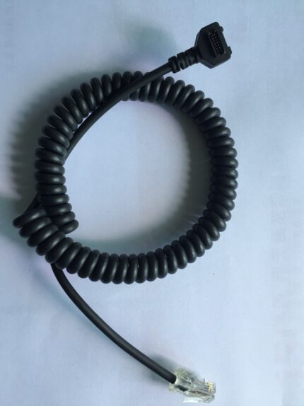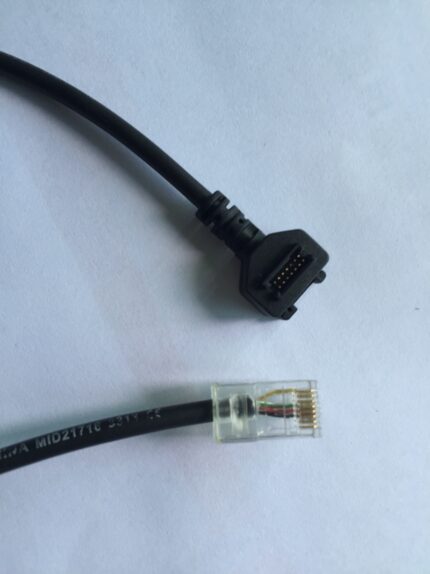
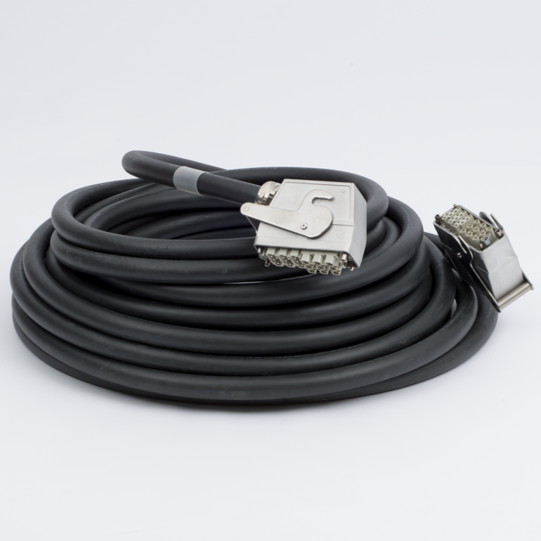
KUKA Robot Power Cable Compatible with MOT X20
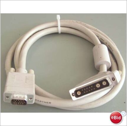
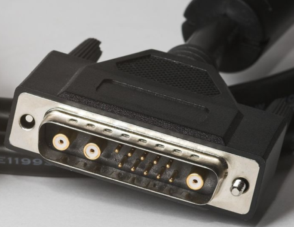
This KUKA MOT X20 cable carries drive power from the controller to the servo motor on KR and VK series robots. Four 14 AWG or 12 AWG conductors under a foil + braid shield, oil-resistant PUR drag-chain jacket, locking motor shell in size 1 or size 2. A compatible replacement, not an OEM part.
Overview
A robot axis only moves because power gets from the drive cabinet to the servo motor, and on the dress pack that run is flexing the whole time. This KUKA MOT X20 cable is the motor power lead wired to the MOT X20 pin layout, built with a high-flex PUR jacket that survives the bend radius inside a cable track and shrugs off the cutting oil that collects there. We build it as a compatible replacement for the original lead – it is not an OEM KUKA part.
Key Specifications
| Connector A | KUKA motor side, size 1 or size 2 power shell, locking |
|---|---|
| Connector B | Controller side, KUKA drive receptacle or open lead |
| Conductor | 4 x 14 AWG or 4 x 12 AWG stranded bare copper |
| Shielding | Overall foil + braid, drain wire |
| Jacket | PUR, black, drag-chain rated, oil-resistant |
| Bend Radius | 10 x OD static, 7.5 x OD dynamic |
| Construction | Center filler keeps the bundle round under flex |
| Length | 5 m to 50 m standard; OEM on request |
| Testing | 100% continuity and pinout, hipot on the finished assembly |
Is your motor shell size 1 or size 2?
The motor end is where a replacement order goes wrong, because the two shell sizes look similar in a photograph and are not interchangeable. Measure rather than guess.
| What you are checking | Size 1 power shell | Size 2 power shell |
|---|---|---|
| How to identify it | Measure across the coupling ring and compare with the old plug | Same measurement, larger shell |
| Conductor options | 4 x 14 AWG or 4 x 12 AWG | 4 x 14 AWG or 4 x 12 AWG |
| Retention | Locking ring | Locking ring |
| What to send us | A photo of the plug face plus the diameter across the ring | Same, plus the motor rating plate |
Does the holding brake ride on the same connector?
Before you order, settle this question, because it changes the conductor count. Some installations carry the motor brake on the same power connector as the phases; others put it on a separate lead. If your motor has a brake and you expect it on this cable, say so up front – we build four conductors to the MOT X20 power layout as standard and add the rest only where the drawing calls for it.
What does 7.5 x OD actually mean in the cable track?
The bend radius figures are not a suggestion; they are the geometry the jacket and the conductor lay are built around. Machine cell wiring is normally specified against IEC 60204-1, and the routing rules it sets are the reason a dress pack has a minimum radius at all.
| Condition | Minimum bend radius | What happens if you go tighter |
|---|---|---|
| Static, fixed after installation | 10 x OD | The jacket takes a permanent set and will not relax |
| Dynamic, moving in a cable track | 7.5 x OD | The outer conductors stretch on every cycle and break first |
| Repeated flex below the dynamic figure | Not rated | Shield braid wears through, then noise gets into the encoder and drive |
| Tight radius plus oil mist | Not rated | PUR survives the oil; the geometry is what fails |
Comparable drag-chain PUR jackets are quoted at 5 million cycles and up, but that figure depends on the radius, the speed and the fill of the track. The cycle life your assembly is built and verified to is the one stated on your drawing.
Why does the original motor lead fail?
- Conductor fatigue at the point where the cable leaves the back shell – the stiffest part of the assembly is also the part that flexes most.
- The shield braid abrades against the inside of the cable track until it wears through, and from that moment the drive starts seeing noise.
- A jacket that is not oil-resistant swells and softens in a machining cell, then splits along the lay of the conductors.
- The bundle goes oval if there is no filler, and the outer conductors take all the strain on every bend.
- Long runs get routed too tight around a corner to save 200 mm of cable, and that corner becomes the failure point.
Specifying a KUKA MOT X20 cable: what we need
- Shell size at the motor end, plus the coupling ring diameter if you can measure it.
- The controller end: KUKA drive receptacle or an open lead for you to terminate.
- Conductor size – 4 x 14 AWG or 4 x 12 AWG – and the motor current it has to carry.
- Length measured along the dress pack route with the arm at full extension, not at rest.
- Whether the brake, and any feedback pair, is on this lead or a separate one. For the feedback side see the KUKA encoder cable build.
Shield termination is the part people skip
A motor power cable is a noise source and a noise victim at the same time. The drive switches kilowatts at several kilohertz, and the encoder and feedback wiring in the same dress pack has to keep working while it happens. That is why the shield on this lead is foil plus braid with a drain wire, and why it has to be terminated into the connector shell at both ends with a full circle of contact rather than a twisted pigtail. A pigtail is fine at DC and useless above a few hundred kilohertz, which is exactly the range the drive operates in. On a retrofit, check how the old cable was terminated before you blame the new one: if the original had a pigtailed shield and the machine ran, the new assembly will only improve things once both ends are landed properly. Route the power lead separately from feedback and encoder cables inside the track where the track allows it, and keep the shield continuous through any intermediate junction.
How the assembly is built and checked
Build standard for KUKA Robot Power Cable builds is IPC/WHMA-A-620 Class 3 under ISO 9001, with terminations from 32 to 12 AWG. No KUKA unit is packed until 100% continuity and pinout check out, and seal checking is quoted whenever an ingress rating is on the drawing.
Lead time and ordering
On KUKA Robot Power Cable builds, prototype lots run from 1 to 50 pcs and leave in 3 working days. Production runs of 500 pcs and up ship 14 working days after approval. Tooling not already held adds around 10 working days. KUKA builds go out under your part number and labeling, and material certificates and first-article reports are on offer.
Related builds
- Custom servo motor cable assembly
- Hybrid servo cable for one-cable solution servos
- Encoder feedback cable with PUR jacket
- OEM servo encoder cable cross-reference builds
- Cobot arm cable harness with drag-chain jacket
- Custom industrial robot wire harness
- FANUC robot teach pendant cable for R-30iB
Full range: custom wire harnesses.
RoHS and REACH declarations are provided per project together with the agreed test reports; the documentation scope is listed under certifications and compliance. If your drawing specifies a UL style, we build to that drawing and supply the UL reference with the shipment instead of substituting an equivalent. For continuous motion the stranding, lay length and jacket are built to the flex method described under continuous-flex construction and flex-life testing, with the cycle count defined in the test scope. Related reading: our test and measurement work. Any tooling we cut for this part stays yours, maintained in our own tool room under your part reference.
Frequently Asked Questions
Is this a genuine KUKA cable?
No. It is a compatible replacement wired to the MOT X20 motor power pin layout, and it is not an OEM KUKA product.
Can you supply it with an open end instead of the drive connector?
Yes. Tell us whether the controller end is a KUKA drive receptacle or a cut lead with stripped and tinned conductors, and what length of tail you want.
What jacket do I need in a machining cell?
PUR, oil-resistant and drag-chain rated, is the default for cells with cutting oil or coolant mist. Where the specification calls it out we can quote the jacket against IEC 60332-1-2 flame propagation.
Can you match a 50 m run?
Yes, and at that length conductor size matters. Send the motor current and we will size the conductors for voltage drop over the run.
| Connector A | KUKA motor side, size 1 or size 2 power shell, locking |
|---|---|
| Connector B | Controller side, KUKA drive receptacle or open lead |
| Conductor | 4 x 14 AWG or 4 x 12 AWG stranded bare copper |
| Shielding | Overall foil + braid, drain wire |
| Jacket | PUR, black, drag-chain rated, oil-resistant |
| Bend Radius | 10 x OD static, 7.5 x OD dynamic |
| Length | 5 m to 50 m standard; OEM on request |
| Construction | Center filler keeps the bundle round under flex |
| Testing | 100% continuity and pinout, hipot on the finished assembly |