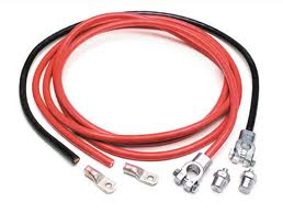
Battery Jumper Lead with Insulated Terminal Clamps
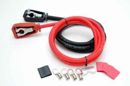
A battery jumper lead with insulated terminal clamps at one end and tinned copper ring lugs at the other, built to your length, gauge and crimp specification.
Overview
A battery jumper lead has one job and one very unforgiving duty cycle: it carries hundreds of amps for a few seconds, then it sits in a boot for six months and is expected to work anyway. That combination is what separates it from a general power cable. The conductor has to be sized for the peak, not for anything average. The clamps have to grip a post that is corroded, tapered and probably slightly the wrong shape. And the insulation on those clamps is a safety feature rather than a comfort feature, because a jumper lead is the one cable in a vehicle that gets connected while the other end is already live.
Key Specifications
| Cable Type | Battery Jumper Lead |
|---|---|
| Jacket | Rubber, per your temperature and flexibility requirement |
| End A | Insulated terminal clamps, positive and negative |
| End B | Tinned copper ring lugs |
| Conductor | Sized per your starting current and run length |
| Clamp insulation | Color-coded insulated handles per your build |
| Polarity marking | Positive and negative identified per your build |
| Testing | 100% continuity and pull force verified in process |
What kills this cable
| Stress | Failure mode | Design response |
|---|---|---|
| Current beyond the conductor’s capability | The cable heats during cranking, the jacket softens, the insulation degrades a little each time | Size to the peak starting current and the run length, not to a catalog default |
| Cold-temperature use | A stiff jacket makes the lead unmanageable exactly when it is needed most | Compound selected for low-temperature flexibility |
| Corroded clamps and posts | High resistance at the jaw, heat, and a lead that cannot deliver what the conductor can carry | Clamp jaw and plating selected for grip; tinned lugs at the fixed end |
| Coiling while still warm | Permanent set and a jacket that cracks at the coil | Jacket selected for recovery, plus a stated minimum coil diameter |
| Reversed connection | Not a cable failure at all, but the reason polarity marking exists | Color-coded insulation and clear positive and negative identification |
Starting current: the duty cycle nobody rates for
A jump-start is a short, very high current event, and it is usually attempted on the coldest morning of the year with a battery that is already flat. Two things follow from that. The conductor has to be sized for the peak, because the starter does not care what the average is. And the jacket has to stay flexible at low temperature, because a lead that will not uncoil is a lead that does not get used.
That is also why length matters more than people expect. Every extra meter adds resistance, and the voltage that arrives at the starter is the voltage that did not get lost on the way. Give us the peak current and the length you actually need and we size to those – not to whatever the last set happened to be.
Clamps, lugs and why the fixed end is different
The clamp end has to grip a post by hand, repeatedly, on a vehicle that is not yours. Jaw profile, spring force and plating all matter, and the insulation on the handles has two jobs: it stops the two clamps touching each other, and it gives a gloved hand something to hold that is not a conductor.
The lug end is permanently connected to a battery, a busbar or a winch feed. That end wants tinned copper ring lugs, crimped with the correct die and sized to the stud, because it is a joint that will be made once and then left in a corrosive environment for years. A tinned lug resists that corrosion; a bare one slowly does not.
Design notes from the build
- Crimp pull force verified at setup for each terminal and wire combination, and re-checked in process.
- Positive and negative identified to your convention – sleeving, lug marking or jacket color.
- Clamp insulation color-coded per your build, and specified for low-temperature handling.
- 100% continuity testing on every lead before packing.
Typical applications for this battery jumper lead
- Emergency jump-start sets for cars, vans and light trucks
- Marine battery bank cross-connections and emergency parallel links
- Fleet and workshop service leads on reels or wall mounts
- Plant, agricultural and construction equipment starting leads
- Generator and auxiliary battery changeover leads, alongside our Heavy-Duty Ring Terminal Battery Lead Cable
- Recovery and roadside assistance kits built to a private-label specification
How to specify your build
- Peak starting current and the length you need.
- Clamp style and jaw rating at the clamp end.
- Lug size at the fixed end, with the stud size.
- Jacket requirement – low-temperature flexibility, oil, abrasion.
- Polarity marking convention, and insulation colors.
- Quantity, and whether this is a retail set or an OEM fitment.
Workmanship and testing
Assembly and inspection follow IPC-WHMA-A-620 Class 3 workmanship criteria under our ISO 9001 quality management system. Every lead passes 100% continuity testing, and crimp pull force is verified at setup for each terminal and wire combination and re-checked in process – on a lead carrying hundreds of amps, a marginal crimp is not a marginal problem. Conductor range is 32 to 12 AWG. Current figures are the ones stated on your drawing; we build and verify to those rather than publishing ratings of our own.
RoHS and REACH declarations are provided per project together with the agreed test reports; the documentation scope is listed under certifications and compliance. If your drawing specifies a UL style, we build to that drawing and supply the UL reference with the shipment instead of substituting an equivalent. Injection parameters for this part are developed against the jacket material using the approach documented under overmolding and injection molding. More background: cable assemblies for automotive and EV. Any tooling we cut for this part stays yours, maintained in our own tool room under your part reference.
Custom builds and ordering
Prototypes start from 1 to 50 pcs and ship in 3 working days; production orders start at MOQ 500 pcs and ship 14 working days after approval. Our Longgang, Shenzhen plant runs four assembly lines with 40 assembly workers and 1,000,000 pcs annual output, and OEM and private-label builds ship under your part number and packaging. Factory audits and video line tours can be arranged.
Related battery and power leads
- Heavy-Duty Ring Terminal Battery Lead Cable
- Heavy-Duty Battery Power Cable with Ring Terminals
- Battery Cable Installation Kit with Terminal Clamps and Lugs
- eBike Battery Harness with XT60, XT90-S or SB50 Plug
- BESS Battery Wiring Harness Built to Drawing for Storage Racks
- DC Plug XT60 Cable with Anderson SB50 Option
Full range: automotive cable and wire harnesses.
Frequently Asked Questions
<div class="
For a related configuration, see the Battery Cable Installation Kit with Terminal Clamps and Lugs.
hkw-faq”>
What gauge should a jumper lead be?
Give us the peak starting current and the length and we will size it. Length matters as much as current, because every extra meter is voltage that does not reach the starter.
Will the cable stay flexible in winter?
It should, and that is a jacket compound decision rather than luck. Tell us the lowest temperature the lead will be handled at and we select for it.
Why tinned copper lugs?
The lug end is a permanent joint in a corrosive environment. Tinning is cheap insurance against the slow resistance climb that eventually looks like a flat battery.
Can you build a set with a carry case and private-label packaging?
Yes. OEM and private-label builds ship under your part number, with packaging and labeling to your specification.
What is the minimum order?
For Battery Jumper builds, prototypes run from 1 to 50 pcs with a 3 working day turnaround; volume orders begin at 500 pcs and ship 14 working days after sample sign-off.
| Cable Type | Battery Jumper Lead |
|---|---|
| Jacket | Rubber, per your temperature and flexibility requirement |
| End A | Insulated terminal clamps, positive and negative |
| End B | Tinned copper ring lugs |
| Conductor | Sized per your starting current and run length |
| Clamp insulation | Color-coded insulated handles per your build |
| Polarity marking | Positive and negative identified per your build |
| Testing | 100% continuity and pull force verified in process |