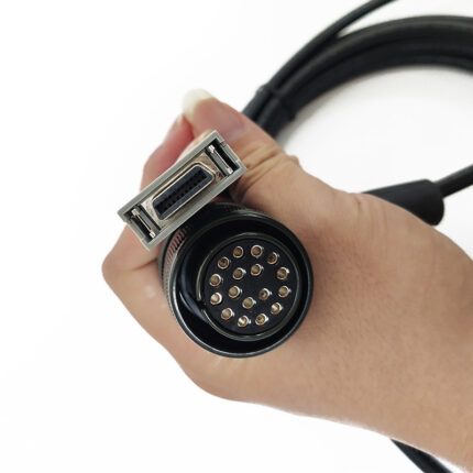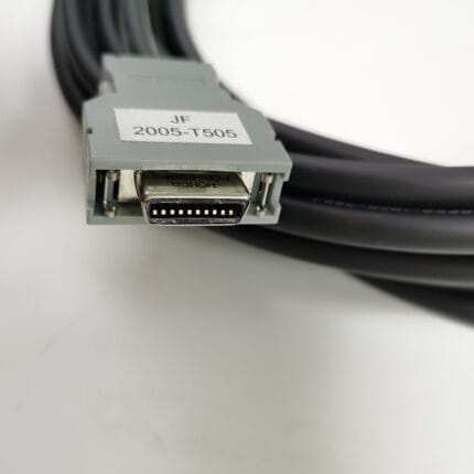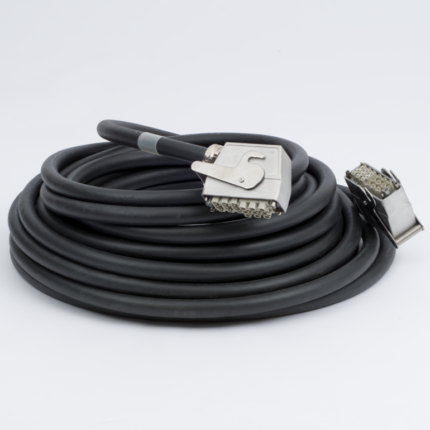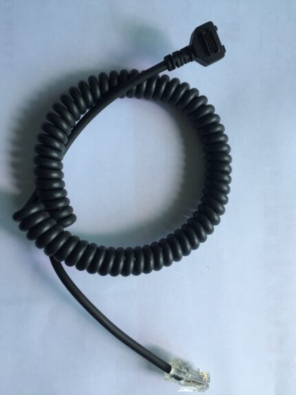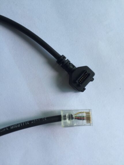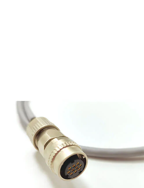
Custom Servo Motor Cable Assembly
A custom servo motor cable assembly that carries power, encoder feedback and brake in one jacket, built to the drive and motor interfaces you name. Send the pinout and the motion profile and we build to it.
Overview
A custom servo motor cable assembly does three incompatible jobs inside one jacket. It carries motor power, which wants copper cross-section and a wide bend radius. It carries encoder feedback, which wants a screen and to be left electrically alone. And on most axes it carries a brake, which wants to switch without throwing a spike into the pair sitting next to it. Almost every servo cable fault we are asked to look at is not a broken conductor – it is the result of those three jobs having been built as though they were one job. We build to the drive and motor interfaces you name, and we separate the power and signal paths in the construction rather than in a note on the drawing.
Key Specifications
| Build | Power, encoder and brake cores in one jacket, per your drive |
|---|---|
| Conductor range | 32 to 12 AWG, sized per circuit on your drawing |
| Power cores | Sized per the motor rating stated on your order |
| Feedback pair | Individually screened twisted pair, or per your drive protocol |
| Shielding | Separate screens on signal, overall braid on power, or both |
| Jacket | PVC, PUR or TPE, selected against oil and flexing duty |
| Flex duty | Fixed install or drag chain; radius and cycles stated per build |
| Terminations | Drive end and motor end connectors per your BOM |
| Length | OEM build to order, 0.5 m and up |
What kills this cable
Before picking materials it is worth naming the four stresses that actually end a servo cable’s life, because each one has a different fix and buying the wrong fix is the expensive part.
| Stress | How it fails | What changes in the build |
|---|---|---|
| Continuous flexing in a carrier | Conductor strands break at the point where the cable leaves the strain relief, not in the middle of the run | Fine-strand conductor, short lay length, overmolded bend relief, radius stated on the drawing |
| Cutting oil and coolant | Plasticizer migrates out of PVC, the jacket stiffens, then it cracks at the bend | PUR jacket, and a compound selected against the specific fluid |
| Drive switching noise | Encoder errors that only appear under load, intermittently, and never on the bench | Individual screen on the feedback pair, 360-degree termination at the connector |
| Torsion on a rotating axis | The bundle twists inside the jacket, cores migrate and the screen opens | Torsion-rated lay-up, braid angle set for rotation, not just bending |
Keeping power and feedback apart
The power cores and the feedback pair are only neighbors by convenience. In the construction they should behave like two cables that happen to share an outer jacket. In practice that means an individual screen over the encoder pair, an overall braid over the whole bundle, and drain wires terminated all the way around the connector shell rather than gathered into a pigtail.
A drain wire bonded with a short tail is the single most common cause of a servo installation that passes bench testing and then throws following errors at load. The tail is an inductor, and at drive switching frequencies an inductor is not a connection. Where the drive maker specifies a shield connection at one end only, we build it that way and say so on the wiring table, so the decision is documented rather than discovered later.
Selecting the jacket and conductor
- PVC – the default for fixed machine wiring. Good flex life when it is not exposed to oil, and the lowest cost per meter.
- PUR – for cutting oil, coolant and drag chains. It costs more and it outlasts PVC by a wide margin in those conditions.
- TPE – where the run sees both low temperature and continuous motion.
On the conductor side, flexing duty is served by more strands of finer wire rather than by more copper. The trade is real: fine-strand conductors cost more, terminate differently and need a crimp or ferrule process set up for them. We run 32 to 12 AWG and size each circuit to the schedule on your drawing rather than to a house standard.
Bend radius and strain relief
Minimum bend radius is normally quoted as a multiple of the cable’s overall diameter, and the multiplier is a function of the construction – a screened hybrid bundle with a large power core will not take the same radius as a thin feedback lead. We state the figure we build to on the drawing instead of leaving it to the installer.
What actually decides service life, though, is where the bend starts. A strain relief that grips the jacket 20 mm away from the connector lets the cable flex at the solder or crimp termination, and that is where the conductor breaks. The overmold is tooled to your connector body so the bend relief begins at the shell, and any load on the cable is carried by the mold, not by the joints.
Design notes from the build
- Break the brake out as a screened pair if it shares the bundle with feedback – an unscreened brake lead next to a feedback pair is a noise injector.
- Clock the right-angle connector to the run. A right-angle body aimed into a cable track turns a gentle bend into a kink.
- Label both ends with the same reference. Servo cabinets get re-terminated during commissioning more often than anyone plans for.
- If the axis is a retrofit, send a photograph of the existing connector faces. The keyway and the insert layout identify the interface faster than a part number search.
Typical applications for this custom servo motor cable assembly
- CNC machine axes, tool changers and rotary tables
- Packaging and converting machines with multiple coordinated axes
- AGV and AMR drive wheels, where the run sees continuous motion and vibration
- Pick-and-place and assembly cells running several axes off one drive rack
- Retrofit work where the original cable is no longer available and the pinout has to be matched, not assumed
- One-cable servo installations, alongside our Hybrid Servo Cable for One-Cable Solution Servo Drives
How to specify your build
- Drive and motor interface – manufacturer and model, or a photograph of both connector faces.
- Pinout – power, encoder and brake, including whether the brake is screened.
- Motion profile – fixed, flexing or torsion, and the carrier radius if it runs in one.
- Exposure – oil, coolant, weld spatter, washdown, temperature range.
- Length, and where along the run an overmolded exit is needed.
- Quantity, and whether this is a prototype or a production release.
Workmanship and testing
Assembly and inspection follow IPC-WHMA-A-620 Class 3 workmanship criteria under our ISO 9001 quality management system. Every unit passes 100% continuity and pinout testing before packing, and screen continuity is checked on shielded builds as part of the same pass. Where a flex life or cycle target is specified on your drawing, that is the target the build is made and verified to; we do not quote a cycle figure of our own and then argue about it later.
Every production run can ship with RoHS and REACH declarations and the electrical report agreed at quotation; see certifications and material declarations. UL styles and other named approvals are built to drawing: we source to the style you specify and document it, rather than asserting a listing we do not hold. Flex life is a construction decision made before tooling, following the conductor and jacket approach set out under high-flex drag chain harness builds. The wider context is covered under cable assemblies for test and measurement. Tooling is quoted separately, cut in-house rather than brokered out, and owned by you.
Custom builds and ordering
Prototypes start from 1 to 50 pcs and ship in 3 working days. Production orders start at MOQ 500 pcs and ship 14 working days after approval, with new overmold tooling adding about 10 working days. We hold 100 sets of mold tooling in house at our Longgang, Shenzhen plant, which runs four assembly lines with 40 assembly workers and an annual output of 1,000,000 pcs. OEM and ODM builds ship under your part number and labeling, and factory audits or video line tours can be arranged.
Related servo and motion assemblies
- Hybrid Servo Cable for One-Cable Solution Servo Drives
- M23 Screw Lock Cable for Servo Motor Power and Encoder Feedback
- M12 M-Coded Motor Cable with Integrated Brake Conductors
- Encoder Feedback Cable with PUR Jacket for Digital Servo Loops
- OEM Servo Encoder Cable Cross-Reference Pages by Machine Family
- M12 Drag Chain Cable for Continuous Flex Cordsets
- Custom Industrial Robot Wire Harness
Full range: custom wire harnesses and signal and data cables.
Frequently Asked Questions
Can you split the power and encoder into two separate cables instead?
Yes, and on long runs or very high power axes it is often the better answer. Two cables cost more to install and need two carrier channels, but they remove the coupling question entirely. We will say so if your layout points that way.
Do you build to a specific drive maker’s pinout?
We build to the pinout you supply. If you have the drive and motor model numbers we can usually confirm the interface from those, but the drawing you approve is the one we build to.
What is the encoder feedback actually for?
The encoder tells the drive where the shaft is, so the drive can close the position loop. That is why the feedback pair gets its own screen: a corrupted position reading becomes a following error, and a following error becomes a stopped machine.
Can you supply the mating receptacles as well?
Yes. Panel and motor-side receptacles are a normal part of the build, with flying leads or a second connector on the back as the installation needs.
What if I only have a sample of the old cable?
Send it, or send good photographs of both connector faces and any print on the jacket. We can reverse-engineer the pinout and build a replacement to match, but the drawing we send back for approval is what governs the production run.
| Build | Power, encoder and brake cores in one jacket, per your drive |
|---|---|
| Conductor range | 32 to 12 AWG, sized per circuit on your drawing |
| Power cores | Sized per the motor rating stated on your order |
| Feedback pair | Individually screened twisted pair, or per your drive protocol |
| Shielding | Separate screens on signal, overall braid on power, or both |
| Jacket | PVC, PUR or TPE, selected against oil and flexing duty |
| Flex duty | Fixed install or drag chain; radius and cycles stated per build |
| Terminations | Drive end and motor end connectors per your BOM |
| Length | OEM build to order, 0.5 m and up |