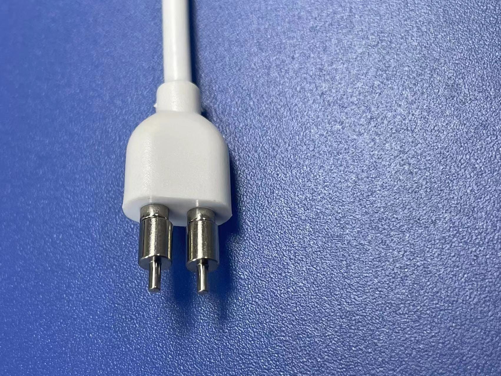
Smart Watch Magnetic Charging Cable with PCBA Tip
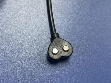
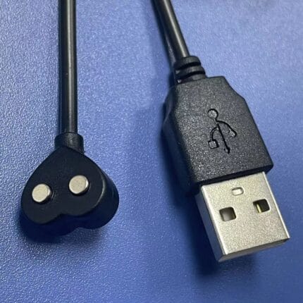
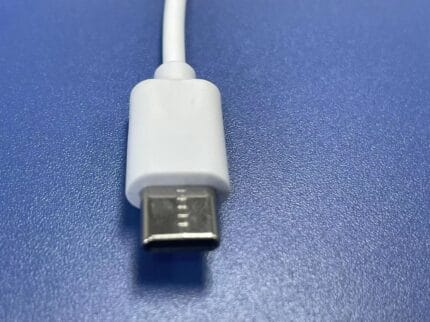
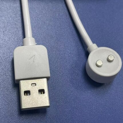
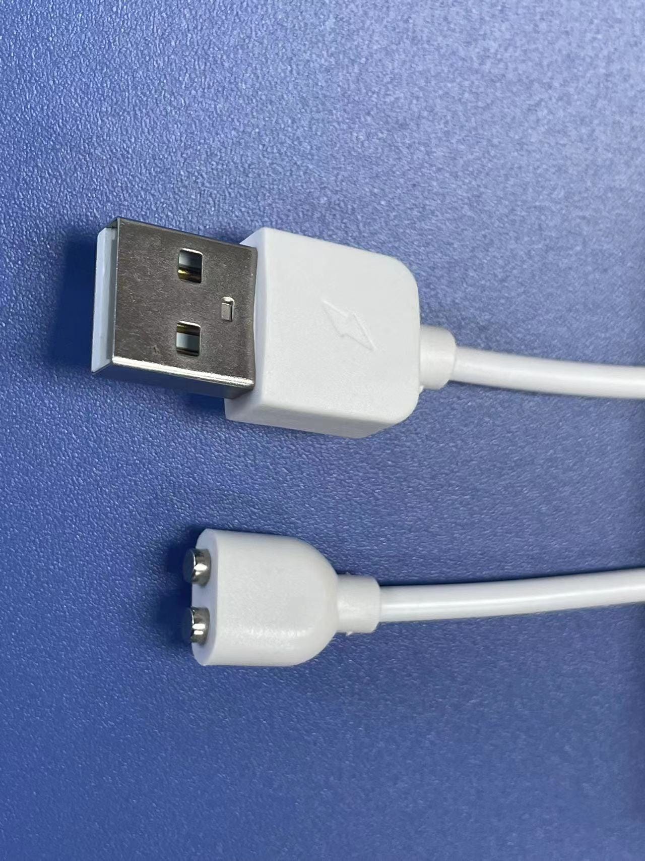
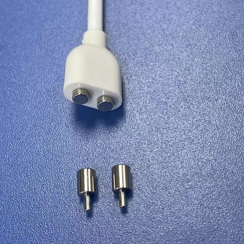
This magnetic smart watch cable carries 5 V from a USB-A host to a magnetic pogo head, with a 2-pin or 4-pin PCBA tip designed into the wearable by the device maker.
PCB footprint and STEP model supplied; length, color and tip layout on request.
Overview
A magnetic smart watch cable splits the charging problem in two. The cable carries 5 V from a USB-A host to a magnetic pogo head. The other half – the small PCBA tip with the matching land pattern – is designed into the wearable by the device maker, so the magnetic head is the only part the end user ever touches. That division is what makes the assembly worth specifying carefully: the tip is a component of your product, not an accessory you buy off the shelf.
Key Specifications
| Connector A | USB-A male host plug |
|---|---|
| Connector B | Magnetic pogo head, 2-pin or 4-pin PCBA tip |
| Tip mount | Through-hole or SMT PCBA tip, custom pin layout |
| Rated voltage | 5 V DC standard |
| Rated current | 1 A standard, 2 A on request |
| Conductor | 2-core or 4-core 26 AWG tinned copper |
| Cable jacket | PVC, 3.0 mm OD, black or white |
| Length | 0.5 m to 1 m standard; OEM on request |
| Head construction | Custom ABS / PC mold, 2 or 4 pogo pins |
| Alignment | Magnet keying; polarity fixed by pin layout |
What your device team has to design in
The tip is a printed circuit board with a pogo land pattern and either through-hole or SMT mounting tabs. It gets assembled onto your device board like any other component, so it has to arrive with the same documentation: a footprint for your layout tool and a 3D model for the enclosure check. We supply both.
| Deliverable | Format | Who uses it |
|---|---|---|
| PCB footprint | Your layout tool, or a neutral exchange file | Hardware layout engineer |
| 3D model of the tip and head | STEP | Enclosure and mechanical designer |
| Land pattern and solder spec | Drawing with dimensions and tolerances | Assembly and process engineer |
| Polarity and pin assignment | Drawing note | Firmware and hardware review |
| First-article samples | Built parts with a report | Validation and qualification |
Give the footprint to your layout team before the enclosure is frozen. The most common rework we see is a device whose board is finished and whose shell leaves no flat area around the tip pads, so the magnetic head bridges on a curve and will not stay on.
Two pins or four
This is the first question to settle, and it is not about data. Four pins let you parallel the power contacts, which halves the resistance of the joint and roughly halves the heat in the head. On a smartwatch that sits against skin, head temperature is a specification, not a comfort issue.
| Configuration | Contacts | When to choose it |
|---|---|---|
| 2-pin | V+ and GND | Low current, small tip area, cost-driven builds |
| 4-pin, power parallel | 2 x V+, 2 x GND | Above roughly 1 A, or where head temperature is specified |
| 4-pin, power plus signal | V+, GND, plus two signal lines | Where the device reports charge state or identifies the cradle |
If you only need power and the current is modest, two pins is the right answer and costs less. Move to four when the load climbs or when the tip has to carry a signal for charge detection.
Where these assemblies fail in the field
- Head will not stay on – the mating face is curved or a bezel stands proud of the pads. Fix is mechanical, not magnetic.
- Intermittent charge – pad finish on the tip wears, or the pogo spring force is too low for the pad plating.
- Warm head – contact resistance times current squared. Split across four pins, or increase the pad area.
- Cable breaks at the head – the strain relief is too short for how users pull the lead off. We can lengthen the boot.
- Reversed magnet – the head seats 180 degrees out because polarity was not keyed to the pin layout on the drawing.
Typical applications for this magnetic smart watch cable
- Smart watches and fitness bands with a magnetic charging cradle
- Medical wearables and continuous monitoring devices
- Hearables and TWS earphone charging cases
- Any small PCBA-powered device that benefits from a breakaway lead
How to specify your build
- Tip pin layout – 2 or 4 pins, pitch and pad size.
- Mounting style – through-hole or SMT.
- Tip PCB size and any keep-out the enclosure imposes.
- Rated current at the device.
- Head color, housing shape and magnet polarity.
- Cable length, jacket color and jacket material.
- Quantity, and whether you need the tip and cable packed separately.
Workmanship and testing
For Smart Watch Magnetic Charging builds the line runs to IPC/WHMA-A-620 Class 3 under ISO 9001, terminating 32 to 12 AWG. Each Smart unit passes a continuity and pinout check before it ships, and seal checking is quoted whenever an ingress rating is on the drawing.
Material declarations against RoHS and REACH are issued per project, alongside the dimensional and electrical reports agreed at quotation; see certifications, compliance and material declarations. Where your drawing names a UL style or another approval, the build follows your drawing and ships with the supporting document rather than a claim of our own. Where this build needs an overmold, the tool is designed, cut and maintained in our own shop under the overmold tooling we build in-house, and it is never used for another customer’s program. Related reading: our marine and outdoor work.
Custom builds and ordering
Smart Watch Magnetic Charging prototype lots start from 1 to 50 pcs and ship in 3 working days; production requires 500 pcs and runs 14 working days after approval. Tooling not already held adds around 10 working days. Private-label Smart runs ship under your part number and labeling, and material certificates and first-article reports are available on request.
Related magnetic and wearable charging leads
- Square-Shape 2-Pin Magnetic Charging Cable
- Heart-Shape 2-Pin Magnetic Charging Cable
- Magnetic Pogo Pin Cable USB-C for Medical and Wearable Devices
- DC 5.5 x 2.1 mm Magnetic Charging Cable
- USB Type-C Magnetic Charging Cable
- 240 W Magnetic USB-C Charging Cable, 16-Pin Rotatable
Related capability: custom wire harnesses built to your drawing.
Frequently Asked Questions
Do you supply the device-side tip?
Yes. We supply the tip PCBA on its own or assembled on your board, and we provide the PCB footprint and a STEP model so your team can lay it out.
Is there a tooling fee?
A tip or head shape we do not already hold carries a mold fee. Standard bodies need no tooling time. We will tell you which applies once we have seen the drawing.
Can the tip carry data as well as power?
Yes, on the 4-pin version, where two contacts are available for signal. Tell us what the signal has to do and we will assign the pins on the drawing.
What is the sample lead time?
Samples run 7 to 10 working days after drawing approval, and production 15 to 20 working days. New molds add to the front of that, not the back.
| Connector A | USB-A male host plug |
|---|---|
| Connector B | Magnetic pogo head, 2-pin or 4-pin PCBA tip |
| Tip Mount | Through-hole or SMT PCBA tip, custom pin layout |
| Rated Voltage | 5 V DC standard |
| Rated Current | 1 A standard, 2 A on request |
| Cable Jacket | PVC, 3.0 mm OD, black or white |
| Length | 0.5 m to 1 m standard; OEM on request |
| Documentation | PCB footprint and STEP model supplied |
Related products
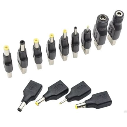
DC Barrel Adapter Kit – 5521 / 5525 / 4017 / 3513 / 1.35mm / 2.5mm, 6-Piece
A dc barrel adapter kit covering 5.5x2.1, 5.5x2.5, 4.0x1.7, 3.5x1.35 and 2.5 mm in six molded female-to-male adapters, so one supply covers a mixed estate. Center positive throughout, with nickel-plated brass contacts. Measure the socket pin with a caliper before ordering: the outer shell is identical across three of these five sizes. Bagged with a size card, or boxed with a printed insert.