M23 17-Pin Encoder Feedback Cable, IP67
This m23 17-pin encoder cable carries the highest-count insert in our M23 feedback range: seventeen signal contacts in a shielded, screw-coupled shell for absolute encoders and multi-turn feedback units on demanding servo axes.
Overview
This m23 17-pin encoder cable carries the highest-count insert in our M23 feedback range: seventeen signal contacts in a shielded, screw-coupled shell for absolute encoders and multi-turn feedback units on demanding servo axes.
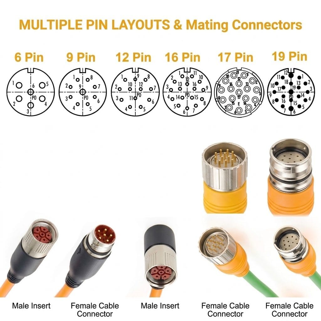
High-resolution absolute encoders need more contacts than a classic feedback insert offers: commutation, multi-turn data, incremental channels and temperature monitoring all land on separate pins. The 17-pin insert covers those dense layouts in one connector, and the same insert series spans 6 to 19 pins so a machine builder can standardize on one shell size across the whole axis.
Key Specifications
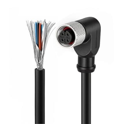
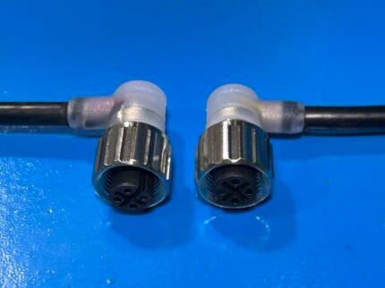
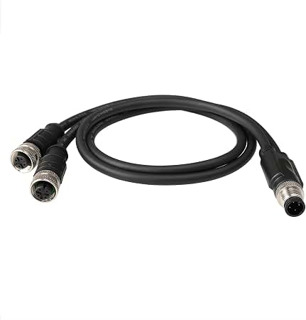
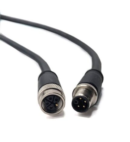
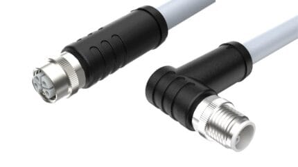
The table below lists the configuration shown in the product photo.
What Seventeen Positions Buy You
A feedback device has more to say than most people expect. It is not simply reporting position: it is reporting position several different ways at once, plus the information the drive needs to commutate the motor, plus what the motor itself knows about its own temperature. Each of those streams wants its own circuit, and several of them want twisted pairs rather than single conductors, so the contact count climbs quickly.
Seventeen positions is what allows that whole set of signals to arrive over one coupling instead of two. A 17-pin layout accommodates absolute position data alongside the incremental channels some controllers still prefer, commutation references for the drive to energize the windings correctly at power-up, the multi-turn record that survives a power cycle, and a thermal sense pair from the winding. Add shielding references and brake control and the pin budget is spoken for.
Where 17-Pin Sits in the M23 Family
The 23 mm M23 shell is shared by three insert families, and knowing which one your machine was built around is the first step in specifying a replacement. Power inserts use a small number of large contacts to carry motor supply. Signal inserts serve encoder and resolver duties, with 12- and 17-position layouts being the common configurations. Hybrid inserts put both contact sizes in one shell.
The insert series here spans 6, 9, 12, 16, 17 and 19 positions, so a machine builder can standardize on one shell size, one panel cutout and one tooling set across an entire range of axes, changing only the insert. Keyways make the different pin counts physically non-interchangeable, which is the safety property that stops a feedback cable being plugged into a power receptacle on a dark plant floor.
Construction and Materials
The insert is crimp-terminated and sealed into the metal shell, with a 360-degree shield termination keeping encoder pulses clean next to motor power cables in the same drag chain. The knurled coupling nut seats against the flange with a positive thread lock, and the overmolded strain relief holds the flexible jacket through millions of chain cycles.
Each contact is crimped rather than soldered so the termination is repeatable across a batch, and the shield braid is terminated 360 degrees to the shell. The strain relief is molded long enough to spread chain flex over the jacket instead of at the crimp.
Crimp tooling is calibrated rather than set by feel, because crimping is one of those processes where the result cannot be verified by eye. Under-crimping leaves a void that oxidizes and raises contact resistance gradually — a failure that shows up months later as intermittent feedback rather than immediately on the test bench.
Typical Applications
Machining centers are the classic install. Spindle drives and feed axes depend on feedback for every dimension the part is held to, and with the feedback circuit running centimeters from motor leads that are switching hundreds of volts, the shield path from motor to drive cabinet is not an accessory but the specification that makes the rest of it work.
Articulated robots use these cordsets on individual joint drives, where the cable sees continuous torsion and the resolver or encoder is reporting joint angle many times per second. Failure here is rarely a clean break; it is drift, jitter, or a drive that trips on following error under load.
Packaging machinery and pick-and-place units run many axes from one controller, and the economics favor a standard insert across every one of them so that a single spare cordset covers any position on the machine.
Printing and converting lines apply them to driven cylinders and registration axes, where synchronization between axes is the product quality metric and any feedback noise becomes visible in the printed result.
Precision positioning stages in semiconductor handling, dispensing and automated inspection sit at the demanding end: fine feedback resolution, tight geometry, and no tolerance for intermittent error that cannot be reproduced on the bench.
Axes inside wind nacelles and tracking equipment use the same interface where the environment, rather than the resolution, sets the requirements: sustained vibration, wide temperature swing, and a service interval that makes a reliable coupling worth more than any single electrical figure.
Choosing Between 12-Pin and 17-Pin
The honest test is the pin map in the documentation, not the count you prefer. If the encoder is absolute and multi-turn, or the drive asks for commutation references plus thermal sensing plus brake control in one connector, the 17-position insert is the one that fits. Incremental encoders with a modest signal set are comfortably served by a 12-position insert, and using the larger body does not make the smaller cable better.
Where a fleet contains both, keep the shell standard and vary the insert. The cost difference is in the insert; the benefit is one panel cutout, one tooling set, and one spare part number for the coupling hardware across every axis.
Compatibility and Fitment
The shell and thread follow the M23 platform dimensions used across industrial drive brands; insert pinouts vary by encoder manufacturer, so match the pin map in your drive documentation before ordering. Confirm male or female gender against your motor connector.
When the motor end is a standard M23 feedback receptacle and the drive expects a D-sub commissioning port, we terminate the second end to suit rather than stacking adapters into a panel that was never designed for them. Send both ends of the circuit and we will build the cable to the actual pair.
Installation and Handling Notes
Keep feedback cable and motor power separated by routing wherever the installation allows. Segregation in a tray costs nothing at build time and cannot easily be retrofitted once the machine ships and the tray is full.
Terminate the shield 360 degrees at both ends rather than relying on a drain wire, and support the cable near the connector so its weight is not carried by the strain relief. On any right-angle exit, respect the bend radius — on these inserts the exit direction exists specifically to keep that bend outside the shell.
Custom Builds and Ordering
Pin assignments, cable classes and lengths are produced to order. Send the encoder datasheet page and we will crimp and test to the exact pin map. Prototype and sample lots run from 1 to 50 pieces; production orders start at 500 pieces per part number.
Packaging and Shipping
Each cable ships bagged with a protective cap over the insert; OEM labels and reel packing are available.
Quality and Compliance
Every contact is continuity and pin-map tested before shipment, and shield termination resistance is checked on the assembly. See the IEC 61076-2-102 M23 connector standard for the governing interface specification.
RoHS and REACH declarations are provided per project together with the agreed test reports; the documentation scope is listed under certifications and compliance. If your drawing specifies a UL style, we build to that drawing and supply the UL reference with the shipment instead of substituting an equivalent. For the sealed version we follow the gasket path and overmold-to-jacket bond practices documented under IP-rated sealing validation. Related reading: what automation programs ask for. Any tooling we cut for this part stays yours, maintained in our own tool room under your part reference.
Frequently Asked Questions
Is 17-pin interchangeable with 12-pin? No. The keyways differ, which is deliberate — it prevents a feedback plug being mated into the wrong receptacle.
Can you build mixed ends? Yes. Give us the motor-side insert and the drive-side port and we terminate each end to match, including D-sub drive ports.
What duty can the cable be built for? Static cabinet runs, continuous drag-chain duty, and torsional duty on rotating joints. Tell us which and the conductor and jacket are specified to it.
Related Cable Ranges
Browse the related ranges: Circular M-Series Cable Assemblies Signal and Data Cables Screw-Lock Molded Cable.
The rest of the M23 feedback family is covered by the M23 encoder feedback cable; where power and feedback share one insert, see the M23 16+3 hybrid servo cable.
| Connector | M23 female cable connector, 17-pin insert |
|---|---|
| Contacts | 17-pin signal layout |
| Coupling | Threaded metal nut |
| Shielding | 360-degree overall shield |
| Ingress Rating | IP67 when mated |
| Family Options | 6 / 9 / 12 / 16 / 17 / 19-pin inserts in the series |
| Application | Absolute and multi-turn encoder feedback |