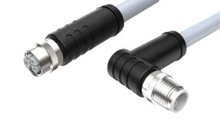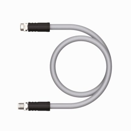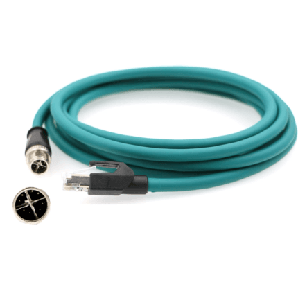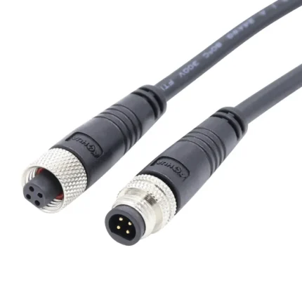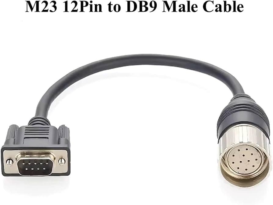
M23 Encoder Feedback Cable, 12-Pin and 17-Pin Servo Cordset
An M23 encoder cable is the quiet half of every servo axis: it carries encoder, resolver and winding-temperature signals from the motor back to the drive, through a 360-degree shield that keeps millivolt feedback legible next to a motor switching hundreds of volts. 12-pin to DB9 drive-end builds are our most common configuration.
Overview
An M23 encoder cable is the quiet half of every servo axis: it carries encoder, resolver and winding-temperature signals from the motor back to the drive, through a 360-degree shield that keeps millivolt feedback legible next to a motor switching hundreds of volts. 12-pin to DB9 drive-end builds are our most common configuration.
Why Feedback Lives on M23
European drive practice settled on M23 for the signal side of motion axes for three reasons. The 23 mm shell holds the 12- and 17-position inserts feedback actually needs, with keyways that make a 12-pin physically impossible to mate into a 17-pin socket. The threaded coupling stays mated under the sustained vibration of a machining spindle. And the metal shell plus clamp-style shield termination forms a continuous Faraday path from motor to drive cabinet – the non-negotiable part when the cable runs centimeters from motor power leads.
What the 12-Position Signal Class Carries
A 12-position signal insert typically runs 150 to 160 V at 8 to 10 A per the arrangement, on conductors from 26 AWG for encoder pairs to 18 AWG for brake and temperature circuits. That is the width of a complete feedback set: incremental A/B/Z channels, commutation Hall pairs, a PT1000 or thermistor pair from the winding, and brake control. Power-position inserts are a separate family at 630 V / 30 A, and mixing the two in one shell is the hybrid build described further below.
Applications for This M23 Encoder Cable: Wherever an Axis Moves Under Command
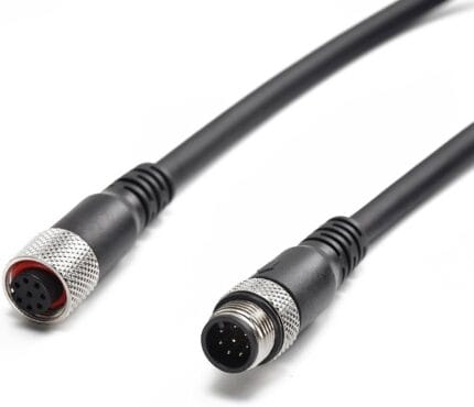
Machining-center spindle and axis servos are the classic install, followed by robot joint drives, packaging machine motion axes, printing cylinders and the precision positioning stages of semiconductor and inspection equipment. The pictured 12-pin-to-DB9 layout is the workhorse for drives whose commissioning port is a D-sub 9 – a common arrangement on inverters and compact servo drives – and for retrofit work replacing a failed molded cable on an existing motor.
The Shield Is the Spec, Not an Accessory
Feedback signals are small; the motor next door is switching hundreds of volts at kilohertz. So the braid is clamped 360 degrees around its full circumference at both connectors instead of gathered into a drain wire, and shield continuity is measured end to end on every assembly rather than assumed. Conductors are finely stranded for the duty you declare – static cabinet run, drag chain, or torsion on a rotating joint.
Power Inserts and Single-Cable Hybrids
The feedback cable and the power cable started as two runs because their inserts are different species – 12 or 17 small signal positions against 6 fat 630 V / 30 A power positions. Modern single-cable-technology hybrids put both inserts in one 23 mm shell with grounded screening between the groups, and we build that too; the ordering discipline is identical, only the insert list changes. For classic installations, keeping feedback and power separate remains the safer default and the lower-cost one.
Ordering From the Drive Side
Start from the drive and motor, not the cable: send both model numbers, or the pinout of the cable being replaced, and we will match the insert and the DB9 pin assignment exactly. Tell us the duty cycle – a six-meter drag-chain run on a robot arm needs different stranding and jacket than a cabinet-to-motor drop – and we return a drawing with final ratings before production. Whole-axis harness sets (power, feedback, brake under one part code) are a standard request.
How Each Assembly Is Verified
Continuity, insulation resistance and hipot are checked on every unit, shield continuity is verified end to end, and sealed builds are leak tested. Connector safety is assessed against IEC 61984 connector safety standard, and test reports plus material declarations ship with each batch.
Related Cable Ranges
Compare the full Circular M-Series Cable Assemblies, the Panel Mount Cable range for cabinet feedthroughs, and Custom Wire Harnesses where power and feedback share one loom.
| Connector series | M23 (M23 x 1.0 coupling) |
|---|---|
| Shielding | 360-degree shield, clamped to shell |
| Jacket material | PUR, PVC |
| Flex duty | Static, Drag chain, Torsion |
| Ingress rating | IP67 when mated |
| Signal positions | 12 (as pictured, to DB9 male), 17, 19 |
| Rated voltage | 150-160 V (12-position signal class) |
| Rated current | 8-10 A (12-position signal class) |
| Wire gauge | 18-26 AWG by position |
| Build style | M23 to DB9 (D-sub 9), M23 to stripped ends, M23 to M23 |