J1708 Diagnostic Cable
A J1708 diagnostic cable is a build-to-print interconnect for a 6-position Deutsch legacy port or the legacy signal pair on a 9-position Deutsch port. Choose a single lead or a two-leg Y splitter; pinout, wire gauge, jacket, length and end treatment are set on the approved drawing. All electrical ratings and pricing are confirm per build or confirm per RFQ.
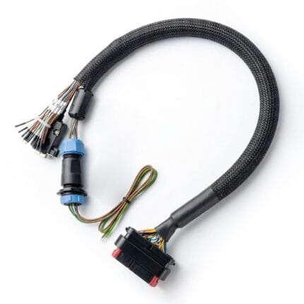
A J1708 diagnostic cable is a build-to-print interconnect for the legacy heavy-duty vehicle data link. It connects a 6-position Deutsch diagnostic port on older trucks and off-highway machines, or the legacy signal pair carried inside a 9-position Deutsch port, to the connector your test equipment uses. We supply the cable assembly only: housings, contacts, conductors, shielding, overmold and strain relief as defined on your approved drawing. Pin assignments, wire gauge, jacket, length and end treatment are set by that drawing, and every electrical rating is confirm per build or confirm per RFQ. Browse the automotive cable and wire harness range, the custom wire harnesses range or the signal and data cables range for related builds.
Overview: J1708 Diagnostic Cable
Heavy-duty diagnostics did not switch connectors all at once. A fleet can hold a 1990s truck with a round 6-position diagnostic port, a 2005 truck with a 9-position port that still carries the older data pair, and a newer truck where only the faster CAN signals are wired. A single cable part number cannot cover all three. That is why we treat a J1708 diagnostic cable as a drawing-driven assembly rather than a fixed catalog item: you specify the port, the wired contacts and the far end, and we build exactly that. The standards named on this page are used as terminology references only; we make no claim of approval or formal compliance against them.
The commercial case is equally practical. Replacing a damaged lead is cheaper than replacing a scan tool connector, and a short extension keeps wear off the vehicle socket. For a mixed fleet, a two-leg Y harness removes the need to carry two separate adapters. Prototype quantities start at 1-50 pieces and volume builds from 500 pieces, confirm per RFQ.
Two Connector Generations: 6-Pin and 9-Pin Deutsch
The 6-position Deutsch port is the earlier generation. Public references place it on pre-2001 Class 7 and 8 trucks, some trailer ABS modules, agricultural and construction equipment, and older buses. It carries the legacy data link and power and ground, with no CAN pair. The 9-position Deutsch port arrived with the wider use of SAE J1939 on heavy-duty vehicles; it is a larger circular connector with lettered contacts and a keyed housing. Both are still in service, which is why an RFQ should always begin with the connector on the vehicle rather than the model year alone.
Referencing SAE J1939-13 for the 9-position diagnostic connector geometry is useful when drawing the housing, but it does not tell you which contacts a particular vehicle actually wired. That information comes from the vehicle wiring diagram or from measurements on the vehicle.
What SAE J1708 and SAE J1587 Define
The legacy link is usually described as a pair of documents rather than one. SAE J1708 is the physical layer, a differential serial link built on RS-485 style signaling at a low fixed data rate. SAE J1587 sits above it and defines the message structure, identifiers and parameter format used by the vehicle modules. Together they formed the diagnostic path on many heavy-duty vehicles before higher-speed CAN networks became common.
For a cable maker, the relevant consequence is physical, not protocol-level: the data line is a differential pair, so it is normally routed as a twisted pair with attention to shield and drain termination. We do not decide the network topology, termination resistors or message timing. Those belong to the vehicle and the equipment designer. Our drawing captures conductor count, pair layout, shield treatment and the connector contacts you specify.
Mixed-Protocol 9-Pin Ports and Type 1 / Type 2 Keying
A 9-position port on a transitional vehicle can expose two different data paths at once. Reference pinouts commonly assign one contact pair to the SAE J1939 CAN high and CAN low signals and a separate pair to the legacy J1708 data lines, with power, ground, shield and manufacturer-specific contacts alongside them. Black and green housings are commonly described as Type 1 and Type 2 keying; they are not interchangeable. Some later vehicles leave the legacy pair unwired even though the connector cavity exists.
That last point matters more than the color of the plastic. If a tool expects a signal on a contact the vehicle never wired, no passive cable can create it. Before releasing a build, confirm on the vehicle which contacts are populated, then put the result into the pinout table. We will not infer a signal map from the connector shape. Confirm per build.
Why the Pinout Cannot Be Assumed
Published 6-position pinout tables disagree with each other. Some list the first two lettered contacts as the differential data pair and later letters as power and ground; others assign power and ground to the early letters; a third group describes a 6-position variant that carries CAN signals instead. Likewise, some 9-position tables swap shield and manufacturer-specific contacts. These are not typos to be resolved by picking one source: they reflect different OEM generations, adapter wiring and equipment-side conventions.
So this page deliberately prints no letter-to-signal map. A J1708 diagnostic cable is released against the customer pinout table and, where available, a sample of the existing lead. If you do not have a table, send the vehicle wiring diagram or a photograph of both connector faces and we will propose one for your approval. Nothing is wired from memory, and no pin position is assumed. Confirm per build.
Cable Construction for a J1708 Diagnostic Cable
The mechanical build follows the environment. A short bench lead can use a slim PVC jacket; a shop-floor lead that is dragged across a bay usually needs PUR or TPE, a tougher strain relief and a molded backshell. Differential data conductors are paired and twisted, with the shield and drain handled according to the drawing. Power and ground conductors are sized on the drawing as well; we do not publish a current rating here. Cable outer diameter, bend radius, exit direction and overmold dimensions are all agreed before tooling starts.
Our overmolded cable assembly specification guide explains how strain relief, jacket bond and mold tooling interact, which is useful when a lead will be plugged and unplugged daily. For a two-leg build, each branch gets its own strain relief and the junction is overmolded or housed as specified.
Splitter and Y-Lead Configurations
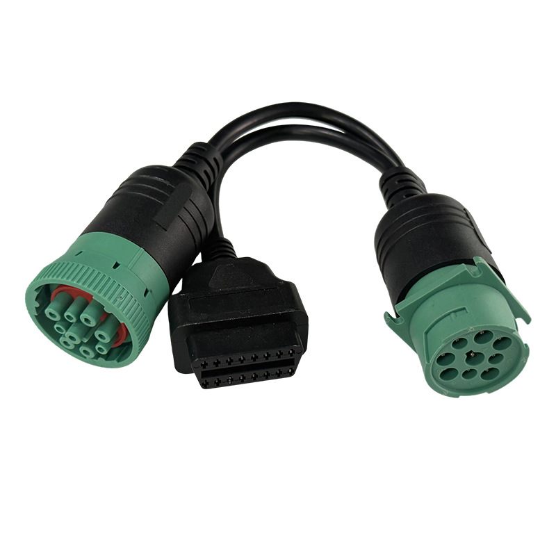
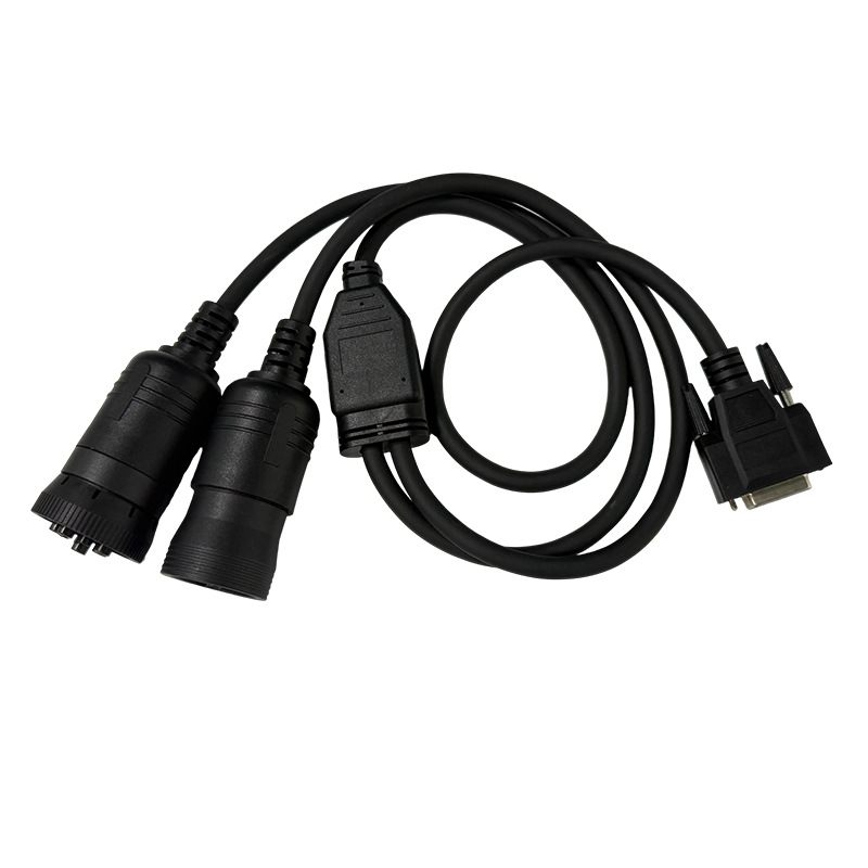
A mixed fleet is the common reason to ask for a Y lead. One leg lands on the older 6-position port and the other on a 9-position port, while the equipment end carries a single connector. Branch lengths do not have to match: a short leg for the dash port and a longer leg for a bench connection is a normal request. Pass-through builds that leave a service tool connected while a tracker stays on the port are another option, and our J1939 9-pin Y splitter and J1939 OBD2 diagnostic cable show related approaches.
Every branch is built to the same pinout table. We do not bridge, repeat or convert signals inside the junction; a Y lead is a passive wiring assembly. If two live tools would contend on the same bus, that is a system design question for the equipment owner, not something a cable can solve.
Reference Configuration Table
The table below is a checklist of decisions, not a published specification. Each line is resolved on the approved drawing before we cut cable or order contacts. It is the fastest way to see what an RFQ still needs.
| Item | Reference configuration |
|---|---|
| Vehicle-side interface | 6-position Deutsch diagnostic port or 9-position Deutsch diagnostic port; confirm per build |
| Signal assignments | Supplied as a customer pinout table; no letter-to-signal map is assumed |
| Contact gender | Plug or socket, straight or right-angle housing; confirm per build |
| Keying and housing | Type 1 or Type 2 keying where a 9-position port is used; confirm per build |
| Equipment-side termination | Molded plug, assembled housing, pigtail or a customer-specified connector |
| Branch configuration | Single lead or a two-leg Y splitter for mixed 6-position and 9-position fleets |
| Conductor count | Set by the pinout table and the shield and drain requirement |
| Wire gauge and colors | Set on the drawing; no gauge or color code is published here |
| Data pair construction | Twisted pair for the differential data line; shield and drain confirm per build |
| Jacket compound | PVC, PUR or TPE; chemical and abrasion requirements confirm per build |
| Cable length and exit | Cut to the drawing, straight or right-angle exit; confirm per RFQ |
| Strain relief | Overmold, backshell or adhesive-lined sleeve; confirm per build |
| Electrical rating | Set by the equipment design and connector datasheet; not published here |
| Test plan | 100 percent continuity, pinout and insulation check; limits confirm per build |
| Order quantity | Prototype 1-50 pieces; volume from 500 pieces; confirm per RFQ |
End Options and Termination
The vehicle end can be an overmolded plug, an assembled housing with a separate backshell, or a socket with flying leads. The equipment end can be a second molded connector, a panel-mount bulkhead, a DB-style connector, stripped and tinned conductors, or a customer-specified terminal. We also build Deutsch DT pigtail harnesses and DT06 to J1939 adapters when the far end is a different connector family. Contact plating, crimp tooling and insertion depth are selected from the chosen connector datasheet, confirm per build.
Right-angle exits are worth specifying early. Under-dash ports are often crowded, and a straight plug can foul a trim panel or put a hard bend into the jacket. A drawing that calls out exit direction and the available clearance avoids a second tooling round.
Test and Verification Plan
Every assembly is checked for continuity, pinout and insulation before it leaves the bench. The test limits come from your drawing rather than from a generic figure on a product page: insulation test voltage, allowable contact resistance and hipot settings are all confirm per build. We record the results against the build number and supply the report when the order requires it.
For a two-leg harness, each branch is verified independently and then as a complete assembly, so a crossed pair in the junction cannot be masked by an end-to-end continuity check. If you need a first-article sample, a golden unit or a photographed test setup, include that in the RFQ and we will quote it with the build.
What This Product Is Not
This is a passive cable assembly, not a scan tool, not a protocol converter, not a software interface and not a vehicle compatibility guarantee. It does not translate between the legacy data link and CAN, and it does not add contacts that the vehicle left unwired. Passenger-car diagnostics use a different 16-position interface described by SAE J1962; that geometry is a separate product family. If your tool expects a passenger-car port, see our J1939 versus OBD2 connector guide before choosing a build.
We also do not publish electrical ratings, protection classes, certificate numbers or brand compatibility lists. Those belong to the connector datasheet and the equipment approval, and any figure on a drawing is confirm per build.
How to Specify a J1708 Diagnostic Cable
Start with five facts: which connector is on the vehicle, which contacts are wired, what the equipment end must be, how long each leg is, and what environment the jacket will see. Add the pinout table, wire gauge and color code, shield and drain treatment, exit direction, overmold dimensions and your test limits. A photograph of the current lead or a sample removes most remaining ambiguity. Send the package through the custom cable assembly RFQ page or contact us directly.
Pricing, tooling and lead time are confirm per RFQ. We do not quote against a vehicle brand or a scan tool model; we quote against the drawing. That keeps the J1708 diagnostic cable scoped to what we actually manufacture and prevents a part number from implying a capability the assembly does not have.
Frequently Asked Questions
Is this built for a 6-pin or a 9-pin Deutsch port?
Either, but they are different builds. A 6-position port belongs to older trucks, trailer modules and off-highway machines that carry the legacy data link only. A 9-position port belongs to newer heavy-duty vehicles and may carry both the higher-speed CAN signals and a legacy J1708 pair on separate contacts. Tell us which port is on the vehicle and which contacts are actually wired, and we build to that drawing. Confirm per build.
Can you guarantee J1708 or J1939 protocol support?
No. This product is a passive cable assembly. It provides the mechanical and electrical connection described by your pinout table. Whether a scan tool can reach a controller, at what data rate, and with which software depends on the vehicle, the tool and the wiring, not on the cable. We make no claim about protocol support, vehicle coverage, approval or formal compliance.
Do you make a 6-plus-9 Y splitter for mixed fleets?
Yes, as a build-to-print assembly. A two-leg splitter lets one tool reach a 6-position legacy port and a 9-position port without swapping cables. The branch lengths, connector genders, keying and the exact contact map all come from your drawing. Send the wiring table and we will quote the harness. Confirm per RFQ.
What do you need to quote a J1708 diagnostic cable?
Send the vehicle-side connector type and keying, a full pinout table, whether the port is a single lead or a Y splitter, the equipment-side termination, wire gauge and color code, shield and drain treatment, jacket, cable length, exit direction and the test limits you want applied. A sample or a photograph of the existing lead helps. Pricing and lead time are confirm per RFQ.
Related Products and Next Steps
Related heavy-duty diagnostic builds include the J1939 Type 1 adapter, the heavy-duty 9-pin industrial diagnostic cable, the J1939 OBD2 diagnostic cable and the J1939 9-pin Y splitter. For a broader comparison of heavy-duty and passenger-car diagnostic ports, read the J1939 versus OBD2 connector guide. All are passive interconnects built to the customer drawing.
Browse the automotive cable and wire harness category or the custom wire harnesses category, then send your pinout table through the RFQ page. Pinout, jacket, length and test limits are confirm per build or confirm per RFQ.
| Vehicle-side interface | 6-position Deutsch diagnostic port or 9-position Deutsch diagnostic port; confirm per build |
|---|---|
| Signal assignments | Supplied as a customer pinout table; no letter-to-signal map is assumed |
| Contact gender | Plug or socket, straight or right-angle housing; confirm per build |
| Keying and housing | Type 1 or Type 2 keying where a 9-position port is used; confirm per build |
| Equipment-side termination | Molded plug, assembled housing, pigtail or a customer-specified connector |
| Branch configuration | Single lead or a two-leg Y splitter for mixed 6-position and 9-position fleets |
| Conductor count | Set by the pinout table and the shield and drain requirement |
| Wire gauge and colors | Set on the drawing; no gauge or color code is published here |
| Data pair construction | Twisted pair for the differential data line; shield and drain confirm per build |
| Jacket compound | PVC, PUR or TPE; chemical and abrasion requirements confirm per build |
| Cable length and exit | Cut to the drawing, straight or right-angle exit; confirm per RFQ |
| Strain relief | Overmold, backshell or adhesive-lined sleeve; confirm per build |
| Electrical rating | Set by the equipment design and connector datasheet; not published here |
| Test plan | 100 percent continuity, pinout and insulation check; limits confirm per build |
| Order quantity | Prototype 1-50 pieces; volume from 500 pieces; confirm per RFQ |
Related products