Patient Monitor ECG Lead Set, 5-Lead AHA
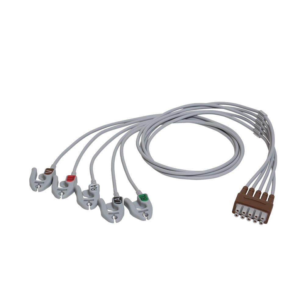
A patient monitor ECG lead set in 5 leads with AHA or IEC color coding, grabber or snap electrodes and a trunk connector built to your monitor pinout.
Last updated: 13 September 2026
Overview
A patient monitor ECG lead set fails at the electrode end, and it fails for a mechanical reason rather than an electrical one: the lead gets pulled, the clip gets trodden on, and the conductor breaks just inside the overmold where nobody can see it. Everything else about the build – the shielding, the color coding, the trunk connector – exists to make that failure happen later rather than sooner, and to make the set behave predictably when it does happen. Ours puts an overmolded strain relief at every electrode and at the trunk, with the color coding moulded into the clip body rather than printed onto a sleeve that rubs off in the wash.
Scope of supply. We manufacture the lead set – leadwire, shielding, electrodes terminations, strain reliefs and the trunk connector – built to your drawing. We do not manufacture the monitor, and we make no claim that this lead set is an approved medical device. The compliance of the finished monitoring system, including its performance under defibrillation, is your responsibility as the device manufacturer. Tell us what your registration requires of the lead set and we build and document to that.
Key Specifications
| Lead configuration | 5-lead, AHA or IEC color coding per your market |
|---|---|
| Lead definition | RA, LA, RL, LL, V – per AHA convention |
| Patient end | Grabber clip or snap electrodes, per your build |
| Trunk end | Connector built to your monitor pinout |
| Cable | Shielded multi-core leadwire |
| Strain relief | Overmolded at every electrode and at the trunk |
| Defibrillation protection | Built to the requirement on your drawing |
| Documentation | Material certificates with lot traceability |
| Scope | Cable component only; finished device compliance is yours |
AHA against IEC: the color coding that causes mix-ups
There are two color conventions in use, and mixing them on a ward is a genuine patient-safety problem rather than an inconvenience. A monitor designed for one market connected to a lead set built to the other will display a trace from the wrong electrode, and nothing about the trace announces that it is wrong.
| Lead | AHA (North America) | IEC (most of the rest of the world) |
|---|---|---|
| RA – right arm | White | Red |
| LA – left arm | Black | Yellow |
| RL – right leg | Green | Black |
| LL – left leg | Red | Green |
| V – chest | Brown | White |
Note that the two schemes use the same five colors and simply reassign them, which is what makes the mix-up so easy and so quiet. We build to whichever convention you specify, we mark the set with the convention it was built to, and we ask you to confirm it on the order rather than assuming from the shipping address.
What kills this cable
| Stress | Failure mode | Design response |
|---|---|---|
| Pulling and treading on the lead | Conductor breaks just inside the electrode overmold; the lead goes intermittent | Overmold geometry cut to the clip, load carried by the boot |
| Repeated cleaning between patients | Jacket crazing and label loss, then fluid ingress at the joint | Compound selected against your cleaning agents; coding moulded in, not printed on |
| Tangling and tight coiling | Permanent set, and eventually a broken core at the coil | Flexible leadwire compound, and a stated minimum coil diameter |
| Mains interference on the ward | Baseline noise that looks like artifact and gets charted as artifact | Shielded cores with the screen terminated properly at the trunk |
| Defibrillation discharge | Damage to the lead set or to the monitor front end | Built to the protection requirement stated on your drawing |
Shielding, noise and defibrillation protection
An electrocardiogram signal is small, and a hospital ward is electrically noisy. Each lead core carries its own screen, gathered at the trunk and terminated to the connector arrangement your monitor expects. Where the monitor design uses a driven right-leg circuit to cancel common-mode interference, that conductor is not just a reference – it is part of the noise cancellation, and it has to be wired as the drawing shows rather than as a generic five-core cable would suggest.
On defibrillation protection: this is a requirement on the finished system, and the component-level approach – series resistance at the electrode, or a specified construction – is set by your design and by the standard your device is registered against. We build to what your drawing states and document what we built. We do not claim a protection level of our own.
Design notes from the build
- Overmold at every electrode, not just at the trunk. The electrode ends take the abuse.
- Color coding moulded into the clip body. A printed sleeve is a consumable; the clip is not.
- Grabber or snap patient ends on the same platform, so a change of electrode style does not mean a new lead set design.
- Trunk connector built to your monitor’s pinout. Every monitor family keys its trunk differently, which is why we ask for the pinout rather than the model name.
- Lot traceability on materials, with certificates issued against the build.
Typical applications for this patient monitor ECG lead set
- Bedside and transport monitors in ward and ICU settings
- Ambulatory and telemetry units where the lead set is worn rather than clipped
- Emergency and pre-hospital monitoring kits
- Veterinary monitors using the same lead conventions
- Training and simulation equipment, where the sets get handled far more roughly than in clinical use
- Cart-based monitoring alongside our Medical Panel Feedthrough Set for Cart and Monitor Enclosures
How to specify your build
- Color convention – AHA or IEC, confirmed on the order.
- Patient end – grabber or snap, and the electrode style.
- Trunk connector and pinout, including any driven right-leg conductor.
- Cleaning agents the set will see between patients.
- Defibrillation protection requirement from your drawing.
- Lead lengths and the trunk length.
- Documentation – material certificates, inspection format, labeling.
Workmanship and testing
Assembly and inspection follow IPC-WHMA-A-620 Class 3 workmanship criteria under our ISO 9001 quality management system, with your acceptance criteria applied wherever your drawing is more specific. Every set passes 100% continuity and pinout testing, and screen continuity is checked in the same pass. Conductor range is 32 to 12 AWG. Any protection or performance requirement is built and verified to the value on your drawing – we do not publish performance figures of our own for a device we do not make.
Custom builds and ordering
Prototypes start from 5 pcs and ship in 3 working days; production orders start at MOQ 500 pcs and ship 14 working days after approval. New overmold tooling for a clip or trunk body adds about 10 working days, and we hold 100 sets in house at our Longgang, Shenzhen plant – four assembly lines, 40 assembly workers, 1,000,000 pcs annual output. Factory audits and video line tours can be arranged.
Related patient-monitoring cable components
- Medical Panel Feedthrough Set for Cart and Monitor Enclosures
- Nurse Call Bedside Cable with Sealed Call Button, USB-C or RJ45
- Nurse Call Button Cable with 6P4C Plug
- Magnetic Pogo Pin Cable USB-C for Medical and Wearable Devices
- Surgical Handpiece Cable with Silicone Jacket
- Ultrasound Probe Cable Assembly, Multi-Coax Build
Full range: custom wire harnesses.
Frequently Asked Questions
AHA or IEC – which do you supply?
Either, but you have to tell us which. The two schemes use the same colors and reassign them, so a mix-up produces a plausible-looking trace from the wrong electrode. We mark each set with the convention it was built to.
Do you supply the monitor?
No. We build the lead set to your drawing. The monitor, the finished system and its regulatory compliance are your scope.
Can you match an existing trunk connector?
Yes, and the pinout is what we need rather than the model name – every monitor family keys its trunk differently. Send the pinout, or a sample if you have one.
Grabber or snap?
Both, on the same platform. Tell us which end style your electrodes use and we build to it.
What is the minimum order?
Five pieces is the prototype minimum and those ship in 3 working days. Production quantities start at 500 pcs, 14 working days after sample approval.
| Lead configuration | 5-lead, AHA or IEC color coding per your market |
|---|---|
| Patient end | Grabber clip or snap electrodes, per your build |
| Trunk end | Connector built to your monitor pinout |
| Cable | Shielded multi-core leadwire |
| Strain relief | Overmolded at every electrode and at the trunk |
| Documentation | Material certificates with lot traceability |
| Lead definition | RA, LA, RL, LL, V – per AHA convention |
| Defibrillation protection | Built to the requirement on your drawing |
| Scope | Cable component only; finished device compliance is yours |