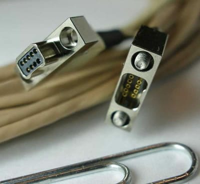
MIL-DTL-83513 Micro-D and MIL-DTL-32139 Nano-D Cable
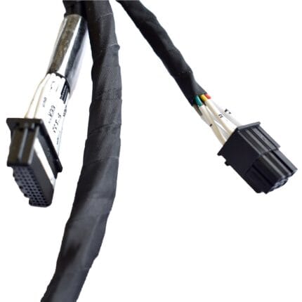
A military micro dtl 83513 assembly on MIL-DTL-83513 Micro-D and MIL-DTL-32139 Nano-D connectors, 9 to 51 contacts at 1.27 mm or 0.635 mm pitch. Shielded, gold-plated contacts, built to your layout.
Overview
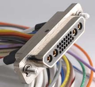
A military micro dtl 83513 assembly is what you use when a D-subminiature shell is too big and a ribbon is too fragile. Micro-D under MIL-DTL-83513 puts 9 to 51 contacts on a 1.27 mm pitch; Nano-D under MIL-DTL-32139 halves that to 0.635 mm for the same contact counts. Both keep the D-sub shell geometry and the jackscrew latching that makes a D-sub hold on, and both are used where grams and cubic centimeters decide the design: airframes, missiles, gimbals, CubeSat and small unmanned platforms. The consequence of that density is that the assembly is delicate, and the harness has to be built accordingly.
Key Specifications
| Connector Family | MIL-DTL-83513 Micro-D / MIL-DTL-32139 Nano-D |
|---|---|
| Contact Pitch | 1.27 mm (Micro-D) / 0.635 mm (Nano-D) |
| Contact Count | 9 to 51 |
| Wire Gauge | 26 AWG to 32 AWG depending on variant |
| Contact Material | Copper alloy, gold plating 1.27 micron typical |
| Operating Temperature | -55 C to +125 C |
| Shielding | Overall foil and braid with drain wire |
| Length | OEM build to required length |
Micro-D or Nano-D: the trade is density against handling
| Micro-D, MIL-DTL-83513 | Nano-D, MIL-DTL-32139 | |
|---|---|---|
| Contact pitch | 1.27 mm | 0.635 mm |
| Contact counts | 9 to 51 | 9 to 51 |
| Typical wire | 26 to 28 AWG, with 24 and 30 available | 30 to 32 AWG |
| Why choose it | Dense, serviceable, and forgiving enough for field repair | Half the footprint and roughly a quarter of the mass |
| What it costs you | Still larger than a Nano-D for the same count | Termination needs magnification and a steady hand; field repair is rarely realistic |
| Where it turns up | Avionics boxes, gimbals, instruments | Missiles, CubeSat, space-constrained payloads |
Contact count against available space
Choosing a contact count is usually a question of what fits on the panel rather than how many signals you have, so it helps to know which counts are standard and what they are normally used for.
| Contact count | Where it is usually specified | What to confirm |
|---|---|---|
| 9 | Serial links, simple sensor heads | Whether one position is used for the shield drain |
| 15 | The general-purpose default | Whether you need the mixed power and signal variant |
| 21 and 25 | Multi-channel instrumentation | Panel cutout and jackscrew clearance |
| 31 and 37 | Dense payload and gimbal wiring | Conductor size against the current per contact |
| 51 | High channel count in a small footprint | Whether a Nano-D would fit the space better |
Where these harnesses actually fail
Not at the contact, and not in the middle of a run. In our experience the failures cluster at the points below, and every one of them has a construction answer you can specify up front.
| Failure | What causes it | What to specify |
|---|---|---|
| Conductor broken at the solder cup | 32 AWG will not take any pulling | Strain relief that clamps the jacket, not the wires, plus a backshell with a proper cable entry |
| Intermittent shielding | A pigtailed drain instead of a 360 degree termination | Braid terminated all the way around into the backshell |
| Intermittent contact under vibration | Jackscrews not torqued, or no locking hardware | Torqued jackscrews with the locking hardware for the series |
| Cracked potting | A rigid compound on a cable that flexes | A flexible potting compound and a defined bend radius at the exit |
| Bent pins | A plug offered up off axis | Keyed shells and a guided mating fixture on the panel |
Construction
- Micro-D or Nano-D shells with the jackscrew or jackpost hardware you nominate.
- Gold-plated contacts terminated with solder cup, PCB tail or pre-wired leads.
- Overall foil and braid with a drain wire, the braid terminated 360 degrees into the backshell.
- Backshell options in top-entry, side-entry and potted styles, with strain relief tied to the jacket.
- Lightweight jacket materials where the mass budget is tight.
What we need from you to quote
- Micro-D or Nano-D, and the contact count.
- Shell style and hardware – jackscrews, jackposts, or a captive variant.
- Termination type – solder cup, PCB tail, or leads, and the wire gauge.
- Backshell – top entry, side entry or potted, and the cable exit direction.
- Length, shielding and quantity, plus whether this is a prototype build.
Typical applications for this military micro dtl 83513 assembly
- Avionics line replaceable units where the panel area is fixed and the channel count is not
- Gimbal and payload wiring, alongside a lightweight UAV wire harness
- Missile and munition harnesses, paired with a Nano-D space harness
- Small satellite and CubeSat builds where mass is the constraint, next to a 38999 high-speed harness for the RF side
- Compact instrumentation, with an ultrasound probe cable assembly as the commercial analogue
Workmanship and testing
ISO 9001 covers the system and IPC/WHMA-A-620 Class 3 covers the work on MIL-DTL-83513 Micro-D builds, across 32 to 12 AWG. Every MIL-DTL-83513 build gets a continuity and pinout check before it is boxed, and seal checking is quoted whenever an ingress rating is on the drawing.
Material declarations against RoHS and REACH are issued per project, alongside the dimensional and electrical reports agreed at quotation; see certifications, compliance and material declarations. Where your drawing names a UL style or another approval, the build follows your drawing and ships with the supporting document rather than a claim of our own. Overmold tooling for this part is designed and cut in our own tool room under the overmold tooling we build in-house, so the tool belongs to your program and a revision is a machining job rather than a new negotiation. More background: how we build and document first articles.
Custom builds and ordering
MIL-DTL-83513 Micro-D lots run from 1 to 50 pcs, out in 3 working days. Volume starts at MOQ 500 pcs shipping 14 working days after sample sign-off. Tooling not already held adds around 10 working days. Your part number and labeling go on MIL-DTL-83513 shipments, and material certificates and first-article reports are on offer.
Related micro and nano harnesses
- Micro-D Shielded Jumper, MIL-DTL-83513
- Nano-D Space Harness, MIL-DTL-32139
- Lightweight UAV Wire Harness
- 38999 High-Speed Harness for Radar and Airborne Ethernet
- MIL-DTL-5015 Circular Power Cable Assembly
Full range: custom wire harnesses.
Frequently Asked Questions
Can you build a hybrid with power and signal contacts in one shell?
Yes, where the arrangement allows it. Send the contact count and which positions need to carry power.
Is 32 AWG too fragile for my application?
It is fragile if nothing carries the strain. Specify a backshell with real cable support and a flexible potting compound and it is perfectly serviceable; hang the weight off the wires and it will not last.
Micro-D or Nano-D for a new design?
Micro-D unless the space genuinely is not there. It is more forgiving to terminate and far easier to repair in the field.
Do you supply the connectors?
Yes, sourced to the callout on your drawing. We also build from free-issued connectors when you already hold them.
| Connector Family | MIL-DTL-83513 Micro-D / MIL-DTL-32139 Nano-D |
|---|---|
| Contact Pitch | 1.27 mm (Micro-D) / 0.635 mm (Nano-D) |
| Contact Count | 9 to 51 |
| Contact Material | Copper alloy, gold plating 1.27 micron typical |
| Wire Gauge | 26 AWG to 32 AWG depending on variant |
| Length | OEM build to required length |
| Operating Temperature | -55 C to +125 C |
| Shielding | Overall foil and braid with drain wire |
Related products