

A USB PD cable gauge is not chosen by wattage. It is chosen by two numbers that a marketing label never shows: the resistance of the power pair in milliohms, and the IR-drop ceiling the USB specification puts on the ground return. Get those two right and 100 W and 240 W cables fall out of a table. Get them wrong and you own a cable that negotiates at 20 V for a laptop but limps at 5 V for a phone — which is the complaint that brings most people to this page.
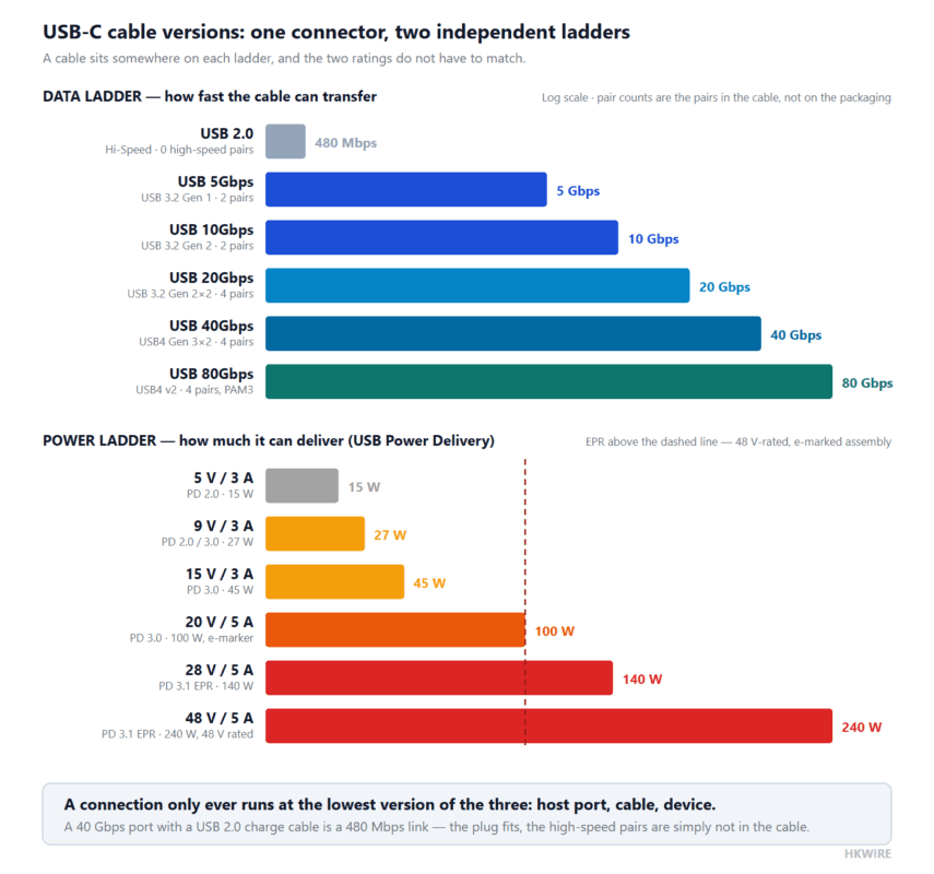
USB-C cable versions are the reason this is confusing. The connector is one shape, but the cable inside it is rated on two independent ladders — a data ladder that runs from USB 2.0 to 80 Gbps, and a power ladder that runs from 5 V / 3 A to 48 V / 5 A. A cable can sit high on one and at the bottom of the other, which is why a “fast charging” cable and a “fast data” cable are frequently not the same cable.
This guide works from the primary documents rather than from rule of thumb: the USB Type-C Functional Test Specification for the cable drop budget, a 240 W reference design from Texas Instruments for the loss comparison, and the USB4 Gen3 plug connector white paper for the data side. All numbers are indicative engineering data — confirm the final construction against the standard and your cable maker’s data sheet.
1. The cable is usually the lossiest link in the chain
Start with what the silicon does. The 240 W USB Type-C and USB PD 3.1 charger reference design (PMP41115) reaches 97.6 % full-load efficiency — a conversion loss of 2.4 %. That is a mature, well-engineered figure, and it is the benchmark any cable should be measured against.
Now the cable. A 1 m 24 AWG power pair at 3 A drops 323 mV per conductor, so 646 mV around the loop. On a 5 V rail that is 12.9 % of the supply.
| Stage | Loss | Comment |
|---|---|---|
| 240 W charger conversion (reference design) | 2.4 % | Full-load efficiency 97.6 %, measured |
| 1 m 24 AWG power pair, 3 A, on 5 V | 12.9 % | 646 mV of 5 V, conductor only |
| Same cable, same current, on 20 V | 3.2 % | The resistance did not change; the rail did |
Charger loss from the TI reference design test report; cable loss calculated from conductor resistance at a 70 °C conductor.
The cable loses about five times as much as the converter it is plugged into — and it is the cheapest, least specified part of the chain. Notice too that the reference design’s own test setup lists “1 m USB Type-C cable (supports 5 A)” as required equipment: even at 240 W, the cable is part of the measurement, not an accessory.
2. The rungs a USB PD cable has to survive
Power Delivery does not negotiate one voltage. It negotiates a rung on a ladder, and each rung makes a different demand on copper. The 240 W reference design supports 5 V, 9 V and 15 V at 3 A and 28 V, 36 V and 48 V at 5 A, with output power capped at 240 W.
| Rung | Power | Range | What it means for the cable |
|---|---|---|---|
| 5 V / 3 A | 15 W | SPR | Mandatory rung; 3 A is the ceiling for an unmarked cable |
| 9 V / 3 A | 27 W | SPR | Phone fast charge; percentage loss still high |
| 15 V / 3 A | 45 W | SPR | Small laptops and docks |
| 20 V / 5 A | 100 W | SPR | 5 A: electronically marked cable required |
| 28 V / 5 A | 140 W | EPR | Higher voltage; cable must be rated for it |
| 36 V / 5 A | 180 W | EPR | Same 5 A copper, higher insulation demand |
| 48 V / 5 A | 240 W | EPR | 5 A plus a 48 V-rated, e-marked assembly |
Rungs as specified in the TI 240 W reference design and the USB-IF Power Delivery documentation. Converters may negotiate additional PPS or AVS windows; evaluate those at the lowest voltage in the window, where the percentage drop is worst.
Two things change the USB PD cable gauge rather than the wattage: 5 A requires an electronic marker, and 28–48 V requires a cable rated for the higher voltage. Everything else is arithmetic on resistance.
3. The rulebook budget every USB PD cable gauge is measured against
Most consumer advice stops at “keep the drop under 5 %”. The specification is stricter and more specific. Assertion 4.4.1#1 of the USB Type-C Functional Test Specification reads:
Divide those ceilings by the cable’s rated current and they become resistance limits — which is what a cable designer can actually build to:
| Rated current | VBUS conductor limit | Ground conductor limit | Both rails together |
|---|---|---|---|
| 3 A | 166.7 mΩ | 83.3 mΩ | 250 mΩ |
| 5 A | 100.0 mΩ | 50.0 mΩ | 150 mΩ |
Seen as a percentage of the rail, the specification is far tighter than the 3–5 % rule of thumb used for industrial DC wiring:
| Rail | 250 mV ground budget is | 500 mV VBUS budget is |
|---|---|---|
| 5 V | 5.0 % | 10.0 % |
| 20 V | 1.25 % | 2.5 % |
| 48 V | 0.52 % | 1.04 % |
The higher the rung, the tighter the budget in percentage terms — the opposite of the intuition that a high-voltage cable has more slack.
4. Turning the budget into copper
With the limits expressed in ohms, USB PD cable gauge selection becomes a lookup. Resistances below are single-conductor values for stranded copper at a 70 °C conductor, using the corrections for stranding and temperature that apply to a loaded cable.
| Power-pair gauge | Area | R per conductor, 70 °C | 1 m drop at 3 A | Verdict at 3 A | 1 m drop at 5 A | Verdict at 5 A |
|---|---|---|---|---|---|---|
| 24 AWG | 0.205 mm² | 107.7 Ω/km | 323 mV | Fails ground | 538 mV | Fails both |
| 22 AWG | 0.324 mm² | 68.1 Ω/km | 204 mV | Passes | 341 mV | Fails ground |
| 20 AWG | 0.518 mm² | 42.6 Ω/km | 128 mV | Passes | 213 mV | Passes |
| 18 AWG | 0.823 mm² | 26.8 Ω/km | 80 mV | Passes | 134 mV | Passes with margin |
Limits applied per the standard’s assertion 4.4.1#1: 250 mV on the ground conductor, 500 mV on the VBUS conductor, at the cable’s rated current.
Read the failure column carefully: in every case above, the conductor that breaks the budget is the ground return, not the supply. A 24 AWG pair rated at 3 A is 270 mV over its own ground ceiling before the VBUS side is even close to its 500 mV. The verdicts are:
- 3 A needs 22 AWG minimum in the power pair, not 24 AWG.
- 5 A needs 20 AWG minimum — and only then with 15 % margin on the ground limit.
- If the construction has more than one conductor per rail (common in 5 A cables), each conductor carries a share of the current and the limits apply to the parallel combination.
Length scales the same way, and this is where short cables get away with thin copper:
| Gauge | Max length at 3 A (ground ceiling) | Max length at 5 A (ground ceiling) | Ceiling that binds |
|---|---|---|---|
| 24 AWG | 0.77 m | 0.46 m | Ground, 250 mV |
| 22 AWG | 1.22 m | 0.73 m | Ground, 250 mV |
| 20 AWG | 1.96 m | 1.17 m | Ground, 250 mV |
| 18 AWG | 3.11 m | 1.86 m | Ground, 250 mV |
5. e-Marker: why 5 A is a different cable, not a bigger number
Above 3 A the cable has to identify itself. The electronic marker is a small chip in the plug that responds to the source’s discovery traffic and declares the cable’s current capability and voltage rating. Three consequences follow, all of them assembly-level:
- It needs to be powered. Each e-marker in a passive or active cable must power up and respond when the source addresses it, and it runs from VCONN — so the assembly has to deliver a clean VCONN path.
- It has an inrush limit. Assertion 4.4.3#4 caps the equivalent inrush capacitance a cable may present to the VCONN source at 10 µF. Aggressive filtering on the marker’s supply is not free.
- It must work at the worst-case drop. Assertion 4.5.2.4.2#4 requires the marker to function with ground and VCONN at their maximum IR drop — tying the chip’s reliability directly to the ground conductor’s resistance.
This is where a USB PD cable gauge on its own is not enough, and where inexpensive “5 A” cables fail: the copper is fat enough to look convincing, but the marker does not complete negotiation at a realistic ground drop, so the port falls back to 3 A or to 5 V. A 5 A cable is a system — copper, marker, plug and termination — and the marker is the part that cannot be inspected by eye.
6. Phones versus laptops: opposite ends fail differently
The two device classes stress cables in opposite ways, which is why a USB PD cable gauge table has to be read per rail, and why “100 W” is a poor predictor of how a cable will behave on a phone.
| Typical negotiation | What it stresses | |
|---|---|---|
| Phone | 5–12 V at 2–3 A | The percentage budget — 250 mV is 5 % of 5 V |
| Laptop | 15–48 V at 3–5 A | The milliohm budget — 5 A leaves only 50 mΩ on the ground |
- A phone is the harder case on a low-voltage rail: thin copper costs it a double-digit percentage of the rail.
- A laptop at 240 W is the harder case on copper: the ground limit halves when the current rises from 3 A to 5 A, so a 5 A cable needs roughly twice the copper of a 3 A cable of equal length.
- Every sink starts on the 5 V rung before negotiating upward, so the 5 V behaviour of a laptop cable still matters — a cable that is marginal there negotiates late or falls back.
The practical rule: specify a charging cable by current capability and by measured loop resistance, never by the wattage in its marketing name. “100 W” describes the best case at 20 V and says nothing about the 5 V rail your phone actually uses.
7. USB-C cable versions: one connector, two independent ladders
Every USB-C cable in the world has the same plug. What differs is what is inside it, and the specification treats that as two ratings that never have to match:
- A data rating — the USB version, from 480 Mbps to 80 Gbps. It is set by how many high-speed pairs the cable contains and how much insertion loss those pairs may accumulate before the link fails.
- A power rating — the USB Power Delivery level, from 15 W to 240 W. It is set by the resistance of the power pair and the ground return, and above 3 A by an electronic marker inside the plug.
That is why “will this cable charge my laptop at full rate?” and “will this cable run my external SSD at full rate?” can have different answers for the same cable. A USB-C cable versions table only makes sense with both columns filled in, because the two columns are chosen on completely different grounds.
The data ladder
| Sold as | Older name | Data rate | High-speed pairs inside | What changes in the cable |
|---|---|---|---|---|
| USB 2.0 | Hi-Speed USB | 480 Mbps | None — one D+/D− pair only | The cable that ships with a charger |
| USB 5Gbps | USB 3.2 Gen 1 (was USB 3.0) | 5 Gbps | 2 — one transmit, one receive | First cable with SuperSpeed pairs and a shield |
| USB 10Gbps | USB 3.2 Gen 2 (was USB 3.1 Gen 2) | 10 Gbps | 2 | Same pair count, half the loss budget per metre |
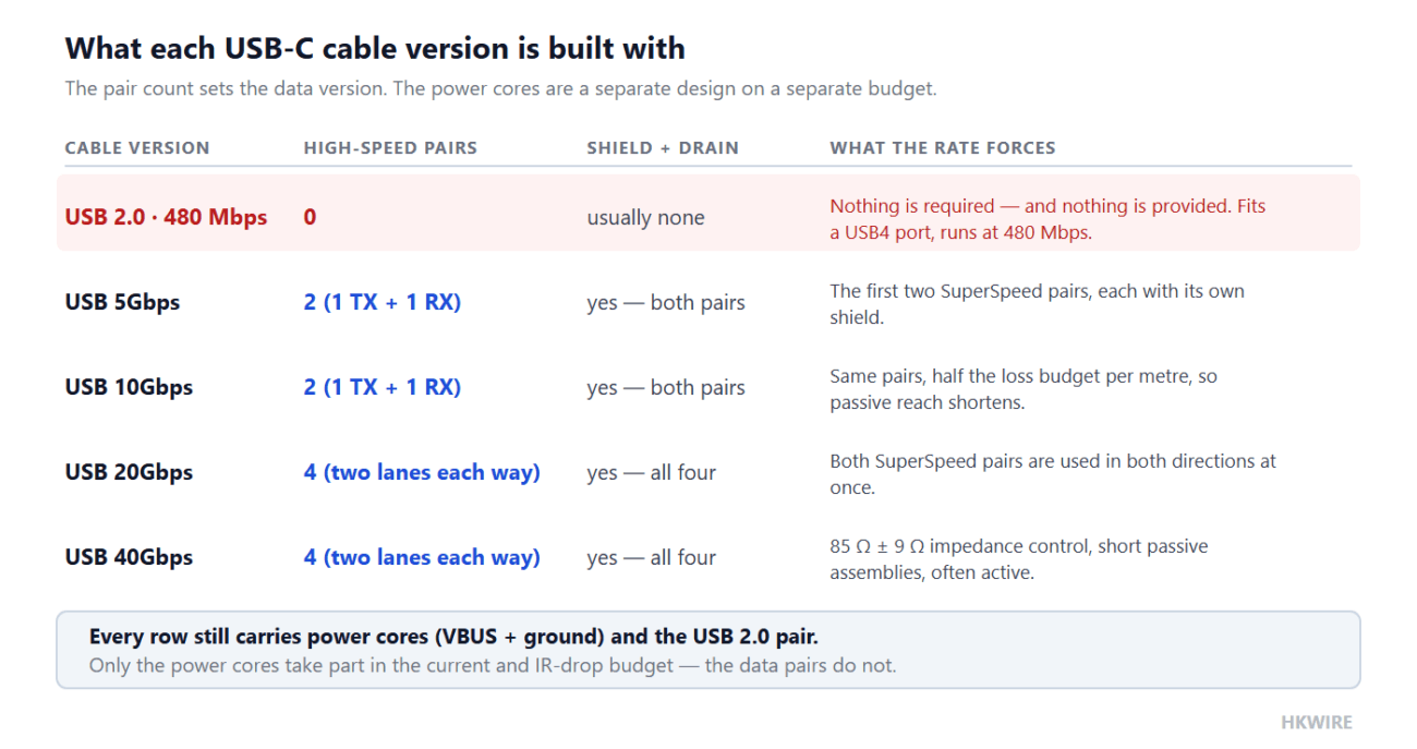
| USB 20Gbps | USB 3.2 Gen 2×2 / USB4 Gen 2×2 | 20 Gbps | 4 — two lanes each way | Both SuperSpeed pairs used in both directions |
| USB 40Gbps | USB4 Gen 3×2 | 40 Gbps | 4 | 85 Ω ± 9 Ω impedance control; short passive assemblies |
| USB 80Gbps | USB4 Version 2.0 | 80 Gbps | 4 | PAM3 signalling; active cable only |
Version names as marketed by USB-IF. The “older name” column matters because the same cable is still sold under USB 3.0, 3.1 and 3.2 labels that no longer mean what they did. Rates are signalling rates.
Two things are worth pulling out of that table. First, a USB 2.0 cable has no high-speed pairs at all. The plug is identical, so it fits a USB4 port, charges a laptop at 240 W, and then runs the connection at 480 Mbps — no amount of port capability recovers a pair that is not in the cable. Second, the pair count stops growing after 20 Gbps: 40 and 80 Gbps cables carry the same four pairs and gain their extra speed from tighter impedance control and better materials, which is where the cost of a high-speed cable actually lives.
The power ladder
| Power Delivery revision | Highest rung | Maximum power | What it adds at the cable |
|---|---|---|---|
| PD 2.0 | 20 V / 5 A | 100 W | Electronic marker required above 3 A |
| PD 3.0 | 20 V / 5 A | 100 W | Programmable supply windows; same copper, same budget |
| PD 3.1 (SPR) | 20 V / 5 A | 100 W | The standard 5–20 V range, unchanged |
| PD 3.1 (EPR) | 48 V / 5 A | 240 W | A 48 V-rated, e-marked assembly — effectively a different product |
EPR = Extended Power Range. Every rung below the top remains reachable, but the cable has to be rated for the highest one it will ever be asked to deliver.
The two ladders meet in exactly one place: the plug. 240 W of EPR power and 40 Gbps of USB4 data can share one connector, and so can 15 W and 480 Mbps. Nothing on the plug tells you which of those you have bought, which is why the cable grade is printed on the packaging and, above 3 A, declared electronically by the marker chip.
What “version” means in practice
A connection always runs at the lowest version of the three things involved: the port on the host, the cable, and the device at the far end. So a 40 Gbps laptop port with a USB 2.0 charge cable is a 480 Mbps connection, and a 240 W charger with a 60 W cable is a 60 W charger. That is the most common source of “my fast cable is not fast” complaints, and it is why we state the data version and the power rating as two separate lines on a drawing rather than one combined “USB-C” description. The pair-level detail behind the data figures is in the next section.
One last naming trap: people searching for USB C cable versions are usually trying to work out whether two cables that look identical will behave identically. They will not, and the label that decides it is the printed data rate plus, above 60 W, the printed power rating — not the shape of the connector.
8. The data side is a separate specification
A USB PD cable gauge decision and a data-pair decision are quoted separately because they answer to different documents. The power pair has an IR-drop budget; the high-speed pairs have a signal-integrity budget. For USB4 Gen3 the plug connector and mated assembly carry the following requirements:
| Parameter | Requirement |
|---|---|
| Differential impedance | 85 Ω ± 9 Ω, measured with a 40 ps (20–80 %) rise time |
| Differential insertion loss fit | ≥ −0.40 dB @ 2.5 GHz · −0.55 dB @ 5 GHz · −0.75 dB @ 10 GHz · −0.90 dB @ 12.5 GHz · −1.10 dB @ 15 GHz |
| Integrated return loss | ≤ −16 dB |
| Integrated differential near- and far-end crosstalk | ≤ −47 dB |
| Differential-to-common-mode conversion (SCD12, SCD21) | ≤ −25 dB, 100 MHz to 10 GHz |
From the USB4 Gen3 plug connector high speed requirements white paper, which also gives design guidance on the ground middle plane and on avoiding voids in the reference ground plane.
Only the last line needs the power engineer’s attention. Differential-to-common-mode conversion is controlled by the ground structure — and the ground structure is the same copper that carries the return current. Thinning the return path to make room for a bigger power pair lowers its resistance but worsens common-mode conversion and insertion loss; the two budgets pull on the same metal. In practice both are set at the paddle card, the small PCB where the cable’s wires terminate inside the plug, which is also where a generous-looking wire list can quietly become a non-compliant assembly.
9. What to put on the drawing
- Current capability stated as 3 A or 5 A, and whether an e-marker is required.
- Voltage rating, explicitly, when any EPR rung (28–48 V) must be supported.
- Power-pair gauge and the maximum resistance per conductor, so the two cannot drift apart.
- The ground conductor’s resistance separately — it carries the tighter of the two budgets.
- Measured loop resistance and the test method used to accept the assembly.
- Data speed class, differential impedance target and the pairs it applies to.
- Strain relief, bend radius and the flex class of the conductors, if the cable is handled.
- Power Delivery revision and data version stated separately, since the two ratings move independently.
Frequently asked questions
Will a 100 W cable charge a 240 W laptop?
Not at full rate. 100 W is 20 V at 5 A; 240 W is 48 V at 5 A. The current is the same, so the copper may be adequate, but the cable must be rated for 48 V and must be electronically marked. A cable that only declares 20 V will limit the port to the 100 W rung.
Is a 24 AWG cable actually rated at 3 A compliant?
Not at 1 m. The ground conductor of a 1 m 24 AWG cable drops about 323 mV at 3 A, against a 250 mV ceiling, so it exceeds the specification on the return path even though the VBUS side passes. It complies below roughly 0.77 m, or if the power pair is 22 AWG. A USB PD cable gauge of 24 AWG simply cannot be rated at 3 A over 1 m. This is the single most common non-compliance in low-cost assemblies.
Why does the ground get half the budget of VBUS?
The specification sets 250 mV for ground and 500 mV for VBUS, and requires the ground limit to hold with VCONN sourced, since the ground carries the additional VCONN return current. The cable’s e-marker must also work with the ground at maximum drop. The tighter return budget protects negotiation and noise, not just efficiency.
Do I need an e-marker at 3 A?
No. 3 A is the ceiling for an unmarked cable. Electronic marking becomes mandatory at 5 A, and EPR operation additionally requires a cable rated for the higher voltage.
Can I check a cable by measuring its resistance?
Yes, and it is the most useful field check. Measure the loop resistance of the power pair with a four-wire method, then compare against the budget for the rated current — 250 mΩ at 3 A, 150 mΩ at 5 A, both rails combined. A cable whose measured loop resistance is comfortably inside that figure will behave as rated; one that is close to it will fall back under load.
Is USB-C the same as USB 3.2 or USB4?
No. USB-C cable versions are two independent ratings. USB-C is a connector shape; USB 2.0, USB 3.2 and USB4 are versions of the data link, and Power Delivery is a separate power specification on top. The same plug can carry a 240 W charge over a USB 2.0 link, or 40 Gbps of data from a cable that charges nothing at all. Read the data rating and the power rating as two independent numbers.
Which USB-C cable versions support 240 W?
Only an assembly built and marked for the 48 V / 5 A Extended Power Range rung, with an electronic marker. 240 W is a property of the cable, not of the connector, so two USB-C cables that look identical can be rated 60 W and 240 W respectively. The rating that applies is the lowest one in the chain of charger, cable and device.
Can I trust a cable labelled “USB 3.1”?
Treat the label as a starting point only. USB 3.1 has been renamed into USB 3.2 Gen 1 at 5 Gbps and USB 3.2 Gen 2 at 10 Gbps, so a “USB 3.1” cable may be either. Check the printed data rate, and for anything above 3 A or 60 W check the printed power rating as well.
At HKWIRE, power and data constructions sit inside the same assembly, so the connector choice matters as much as the wire list: see the screw-lock molded cable range for vibration-resistant USB and data assemblies, custom wire harnesses for multi-conductor looms, and custom development when the plug has to be molded around the cable. Because USB-C cable versions are quoted on two ladders, we state both on the drawing: data version and pair count, power rating, and the ground conductor’s resistance.







