

A panel mount connector, also called a bulkhead or flange connector, is the half of the link that lives on the enclosure wall. The catalog decisions get the attention: mounting style, coupling mechanism, IP class, cable side. The failures that come back from the field are arithmetic instead. Too little thread engagement. A cutout that is nominally correct and assembles wrong. A gasket that never reached its working compression because the panel sat at the end of its thickness tolerance. This guide works the four catalog decisions, then the two calculations that decide whether the part is still on the wall next year: thread engagement and shear, and the cutout tolerance chain.
HKWIRE builds panel mount receptacles and the mating overmolded cable plugs as a matched pair, so the numbers below are the ones we ask for in an RFQ. If you take only one idea from this page: the connector is not the joint and it is not the seal. The panel, the gasket and the length of thread that actually ends up engaged are the joint.
How a panel mount connector is specified
On any panel mount connector the interface has three jobs, usually owned by three people: hold the shell against pull-out and rotation, seal the wall at the flange and at the cable entry, and present a repeatable mating face a technician can mate blind without a torque wrench.
Two of those jobs reduce to one number. Pull-out, back-off under vibration and seal preload all pass through the engaged thread, so the useful question is not which connector but how many millimeters of thread are still engaged after the panel, the gasket and the nut have taken their share. That number is L_e, and it is the subject of the calculation below.
One structural fact kills a whole class of field problems. On a panel mount connector the thread is fixed; on a cable-end connector the coupling nut is free to rotate. Two panel mount connectors therefore cannot be mated to each other, because neither thread can turn. Gender does not change this: male and female panel parts both have fixed threads.
1. Front mount vs rear mount
The mounting styles for a panel mount connector differ in where the flange sits and in what sets the engaged thread length and what access you need at assembly.
| Style | Where the flange sits | What sets the engaged thread length | Access required after fitting |
|---|---|---|---|
| Front mount | Outside face, nut inside | Nut height, or the panel if the panel is tapped | Inside access at assembly to fit and hold the nut |
| Rear mount | Inside face, flush outside, nut outside | Nut height, or the panel if the panel is tapped | Outside access at assembly; flange captive inside |
| Through-hole / jam nut | Body passes through, hex or flats outside | Nut height (the panel is clamped, not threaded) | Both faces during assembly, one face for re-torque |
| Tapped panel, no nut | Flange seats on the panel face | Panel thickness – this is the case that fails | None after fitting; the connector cannot be re-torqued |
Read the third column again. With a jam nut the engaged thread length is the nut’s own height (a standard ISO 4032 M12 hex nut is 10.8 mm tall), so a 1 mm panel and a 6 mm panel give the same thread joint. With the thread tapped directly into the wall the engaged length is the panel thickness, and a 3 mm cover wall gives 3 mm of thread no matter what the connector cost.
The “easy to install” question is really two. Which face can you still reach after the enclosure is welded, glued or powder-coated? If only the outside is reachable, a rear mount is out unless the connector is fitted before the enclosure closes. And how much room is left behind the panel for the nut and the cable’s bend radius? A rear mount also keeps the outside face flush, which is worth paying for on washing equipment.
2. Coupling mechanism
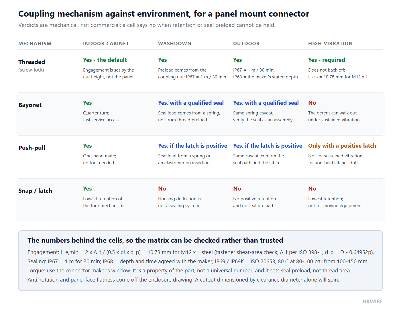
Coupling on a panel mount connector is a retention decision, and it also determines where the axial preload that compresses the seal comes from.
| Mechanism | Retention principle | Mating action | Where seal preload comes from | Vibration behavior |
|---|---|---|---|---|
| Threaded (screw-lock) | Thread friction plus axial preload | Multiple turns of a coupling nut | The coupling nut, turned down against a face | Does not back off; the safe default on moving equipment |
| Bayonet | Spring detent in a groove | Quarter turn | A spring, not a screw thread | Can walk out of the detent under sustained vibration |
| Push-pull | Latch or collet, released by a sleeve | Straight push, straight pull | A spring or elastomer, compressed on insertion | Good if the latch is positive; poor if it relies on friction |
| Snap / latch | Plastic detent | Straight push | Housing deflection on insertion | Lowest retention of the four; not for repeated handling |
For moving or vibrating equipment, threaded screw-lock is the safe default, because the axial preload that holds the joint comes from thread friction rather than from a spring.
Anti-rotation is part of the cutout, not an accessory
A circular connector on a circular hole is free to spin, and a shell that spins inside the hole turns your tightening torque into nothing instead of into axial preload. The keying therefore belongs on the cutout drawing, with a tolerance. The three common ways to do it are a double-D cutout, a hex or double-flat body in a matching cutout, and an anti-rotation pin in a second hole, which suits thin panels and non-metallic enclosures where a tight flat-to-flat would crack the panel. Whichever you choose, the cutout drawing must define the shape and the tolerance on every dimension that resists rotation, not only the diameter that clears the thread.
The torque belongs to the connector maker
Every coupling mechanism has a torque window, set by the maker, not by feel. The lower bound develops enough axial load to compress the seal across the temperature range. The upper bound is where the shell, the thread or the panel starts to yield. Ask for both bounds and put them in the work instruction. A joint torqued past the window flattens the gasket permanently, and the second assembly leaks even though the first one passed.
3. IP and sealing
The IP code of a panel mount connector is a pair of digits under IEC 60529. The first covers solids and contact, 0 to 6, where 6 means dust-tight. The second covers water, 0 to 9. The water digits are not one ladder: jets (5, 6) and immersion (7, 8) are different tests, so a part rated for immersion has not necessarily passed a jet test, or the reverse. That misunderstanding accounts for most IP arguments.
| Code | What it protects against | Test condition | Where it fits a panel |
|---|---|---|---|
| IP20 | Fingers, 12.5 mm objects; no water rating | No water test performed or declared | Inside a dry cabinet |
| IP54 | Dust-protected (limited ingress); splashing water | Spray or splash from all directions | Sheltered indoor equipment, no washdown |
| IP65 | Dust-tight; low-pressure jets | 6.3 mm nozzle, about 12.5 L/min, 2.5 to 3 m, at least 3 min | Outdoor enclosures that get hosed |
| IP66 | Dust-tight; powerful jets | 12.5 mm nozzle, about 100 L/min, 2.5 to 3 m | Marine and heavy washdown duty |
| IP67 | Dust-tight; temporary immersion | 30 min in fresh water; lowest point of the enclosure at least 1 m below the surface, highest point at least 150 mm below it | The default outdoors and where flooding is possible |
| IP68 | Dust-tight; continuous immersion | Agreed between maker and user, and more severe than IP67. Depth and time are not fixed by the standard | Submerged equipment only; get depth and duration in writing |
| IP69 / IP69K | Dust-tight; close-range hot high-pressure jets | From ISO 20653 (originally DIN 40050-9): 80 degrees C water at 80 to 100 bar, nozzle 100 to 150 mm, 14 to 16 L/min, four angles 30 s each | Food, pharmaceutical and vehicle equipment that is steam-cleaned |
Two consequences follow from reading the test conditions rather than the label. “IP68” alone is not a specification: the standard defines the IPX8 test as continuous immersion under conditions agreed between the manufacturer and the user, requiring only that they be more severe than IP67, so one maker’s IP68 may be 1.5 m for 30 minutes and another’s continuous at 10 m. And IP69K is not IP68 plus more. It comes from ISO 20653, and a jet at 80 to 100 bar can displace a soft seal that holds under the slow pressure of immersion. If the equipment is both submerged and pressure-washed, you need both ratings, tested independently.
Mated and unmated are two different ratings
Almost every panel-rated connector is rated only when mated. An IP67 receptacle with nothing plugged into it is an open barrel of exposed contacts sitting in whatever your process uses. If the port spends time open, the bill of materials has to include a dust cap with its own rating and retention.
The rating belongs to the assembly, not to the connector. A receptacle can carry IP67 from its maker and still leave your panel leaking, because the wall is only one of two seal paths; the second is the cable entry, created when the jacket bonds to a molded boot or compresses in a gland. So a drawing should say “IP67 with a 4.0 to 6.5 mm outer diameter cable fitted”, not “IP67 connector”.
The seal is a compression system
A gasket seals by being squeezed, and four things have to be true at once: the flange has the right depth, the elastomer lands inside its working compression range, the panel face is flat enough over the seal path, and the joint is torqued enough to hold that compression. Nitrile and silicone are not interchangeable – they differ in temperature range and compression set, so choose against the temperature at the panel face, not the room.
Panel face flatness is the one that gets forgotten. On a welded enclosure the area around the cutout is often the least flat part of the box, so a seal validated on a milled test plate leaks on the real one. If the panel is welded sheet, say so in the RFQ.
4. The cable side: field-mount vs overmolded
A panel mount connector only does half the job; the other half is the plug that mates with it. A field-mount plug is terminated on site. It lets you shorten a cable to length, and it suits low volumes and repairs. The cost is variance: the seal and the strain relief are only as good as the assembler.
An overmolded cable plug is molded onto the cable in the factory. The jacket is bonded to the boot, the strain relief geometry is fixed by a tool rather than by technique, and every unit is the same. For production volume and harsh duty we recommend the overmolded side, because the cable entry is the second seal path and a bonded jacket-to-boot interface is a seal by design rather than by assembly skill. The trade is that the assembly cannot be re-terminated in the field. See our notes on how to specify an overmolded cable assembly and on what engineers should define in an overmolded design.
5. Pin count, coding and gender
On a panel mount connector, pin count is a signal and power count, not a preference. The M8 and M12 families in the IEC 61076-2 series cover 2 to 17 contacts depending on coding, and the coding – not the pin count – decides what the connector may legally be plugged into.
| Coding | Standard | Contacts | What it is for |
|---|---|---|---|
| M12 A | IEC 61076-2-101 | 3 to 5, and 8 or 12 in specific variants | Sensors, actuators, DC power, general signal |
| M12 B | IEC 61076-2-101 | 5 | Non-Ethernet fieldbus, commonly Profibus DP |
| M12 C | IEC 61076-2-101 | 3 to 6 | AC power, including motor connections |
| M12 D | IEC 61076-2-101 | 4 | Industrial Ethernet at 100 Mb/s, two pairs |
| M12 X | IEC 61076-2-109 | 8 | Ethernet to 500 MHz, used for 10 Gb/s links |
| M12 power: S, T, K, L, M | IEC 61076-2-111 | 2 plus PE through 5 plus PE | AC and DC power transmission |
| M12 Y | IEC 61076-2-113 | 8 | Power plus 100 Mb/s Ethernet on one connector |
Every coding has its own keyway, and the keyway is the point: two parts with the same contact count and different codings will not go together, which stops a technician plugging a sensor cable into an Ethernet port. Within a family, contacts can also be omitted to create a differently keyed variant, so “same pin count” is never a compatibility statement. Gender is separate: the receptacle is the fixed half and the plug the free half, and both exist in male and female contact versions, so define coding and contact gender on both ends and check that you ordered a mating pair. Our M12 coding guide maps each code to its protocol.
The panel cutout: a tolerance chain, not a diameter
Here is the failure that no catalog diagram of a panel mount connector shows. Every dimension is inside its tolerance, every part is to print, and the joint still has less thread engagement than the calculation asked for. Nothing is out of tolerance; the tolerances stack in the same direction. The thread on the body is only useful for the part still exposed after the panel and the gasket have taken their share.
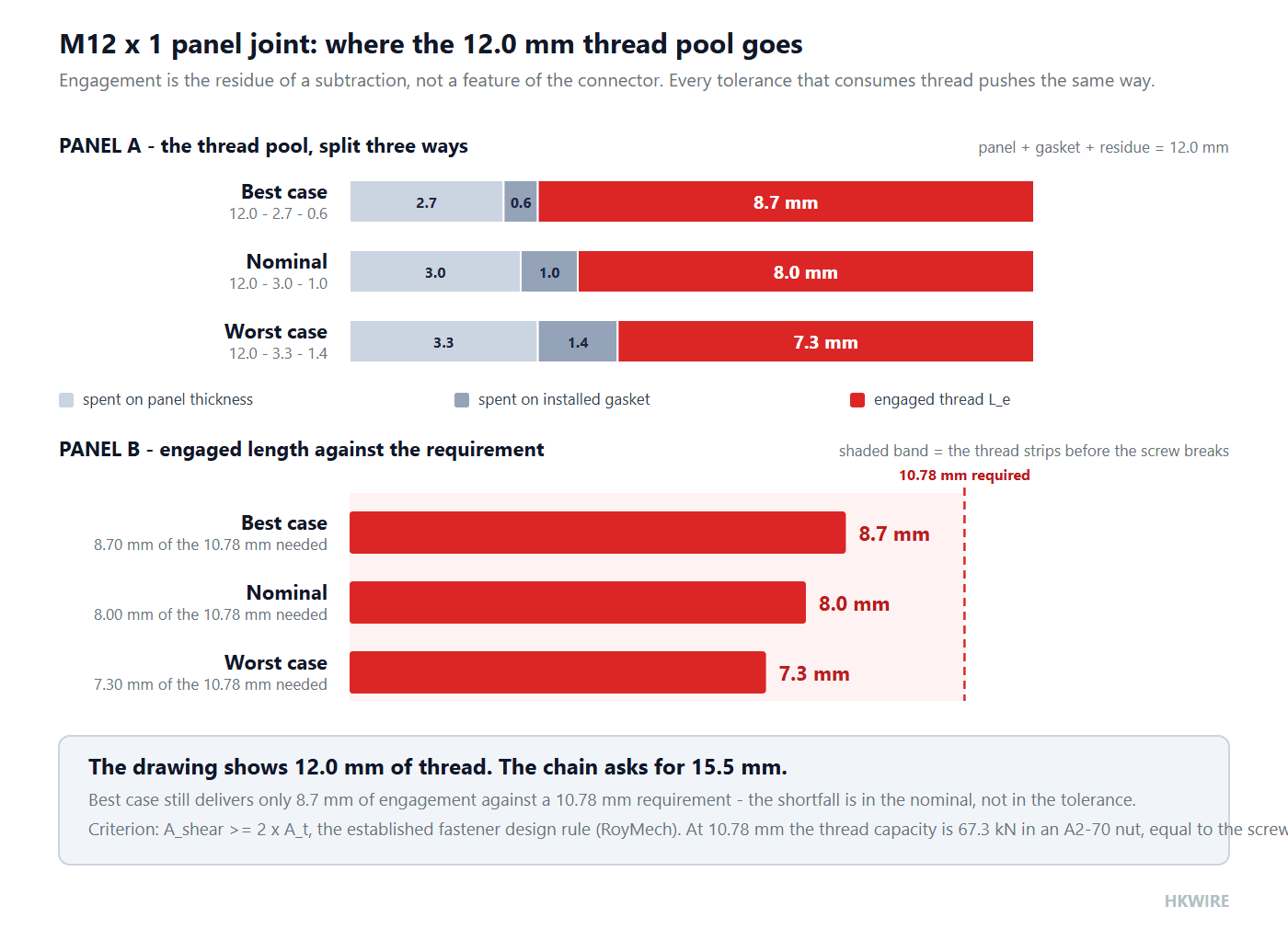
| Element in the chain | Nominal | Tolerance / range | Effect on engaged thread length |
|---|---|---|---|
| Thread length on the body behind the flange face | 12.0 mm | Per the connector maker’s drawing | This is the pool |
| Panel thickness | 3.0 mm | plus or minus 0.3 mm, so 2.7 to 3.3 mm | Spends thread one for one |
| Installed gasket thickness (flat gasket, flange to panel) | 1.0 mm | plus or minus 0.4 mm, so 0.6 to 1.4 mm | Spends thread one for one |
Engaged thread length L_e, best case | – | 12.0 – 2.7 – 0.6 = 8.7 mm | Still short of the requirement |
Engaged thread length L_e, nominal | – | 12.0 – 3.0 – 1.0 = 8.0 mm | Still short of the requirement |
Engaged thread length L_e, worst case | – | 12.0 – 3.3 – 1.4 = 7.3 mm | 32 percent below the requirement |
| Required engaged thread length for M12 x 1 (from the calculation below) | – | 10.78 mm | The failure is in the nominal, not in the tolerance |
| Required thread length on the body, worst case | – | 10.78 + 3.3 + 1.4 = 15.5 mm | The drawing needs 15.5 mm and shows 12.0 mm |
Substitute your own numbers; the method is the point. Note the pattern: every contributor pushes engagement down, because every one of them consumes thread. The stack is one-sided, and the spread from best to worst case is 1.4 mm, or 13 percent of the required engagement.
One variation is worth designing out. If the gasket sits in a captured groove rather than flat between flange and panel, its thickness never enters the chain, so the pool is the full 12.0 mm minus panel thickness.
The thing that general guides, AI summaries and online calculators leave out. They will give you a cutout diameter and an IP code. They will not tell you that the joint is governed by L_e, that L_e is the residue of a subtraction rather than a feature of the connector, or that the residue is normally smaller than the nominal difference between two parts. Ask any supplier for the thread length behind the flange as a drawing dimension; if it is not on the drawing you cannot calculate the joint.
Thread engagement and shear: the calculation nobody runs
The engaged thread fails by stripping, not by breaking. Stripping is sudden and gives no warning, so every engineered threaded joint is designed the other way round: the screw should break before the thread strips, because a broken screw is obvious and a stripped thread hides until the joint lets go.
The formula
Start from the basic thread geometry. For an ISO metric thread the pitch diameter, where thread width equals space width, follows from the nominal diameter D and the pitch p:
d_p = D - 0.64952 x p
The shear area of the internal thread over an engagement length L_e is the cylindrical strip of thread flanks at that diameter. The standard fastener approximation is
A_shear = 0.5 x pi x d_p x L_e
and the load the thread carries is that area times the allowable shear stress. For thread stripping, the conservative factor used in the established fastener method is half the tensile strength:
F_shear = A_shear x tau_allow, with tau_allow = 0.5 x R_m
Now the design criterion. Thread shear strength is about half of tensile strength, so for the screw to be the weak link the shear area must be at least twice the screw’s tensile stress area A_t:
A_shear >= 2 x A_t, with the ISO 898-1 tensile stress area A_t = (pi / 4) x ((d_p + d_3) / 2)^2 and d_3 = D - 1.22687 x p
Substituting gives the minimum engagement length, which is the number you want on the drawing:
L_e,min = 2 x A_t / (0.5 x pi x d_p)
These expressions, and the more precise FED-STD-H28/2B and Machinery’s Handbook form of the same calculation, are set out in the RoyMech thread and engagement reference. The ISO 724 thread dimensions used below are tabulated in this metric thread dimension chart, and thread material strengths for stainless fasteners come from the property classes in ISO 3506.
Worked through for M8 and M12
| Thread | D (mm) | p (mm) | d_p = D – 0.64952p | A_t (mm2) | A_shear per mm (mm2/mm) | L_e,min (mm) | L_e,min as a multiple of D |
|---|---|---|---|---|---|---|---|
| M8 x 1 | 8.0 | 1.0 | 7.350 mm | 39.2 | 11.55 | 6.78 | 0.85 x D |
| M12 x 1 (fine) | 12.0 | 1.0 | 11.350 mm | 96.1 | 17.83 | 10.78 | 0.90 x D |
| M12 x 1.75 (coarse) | 12.0 | 1.75 | 10.863 mm | 84.3 | 17.06 | 9.88 | 0.82 x D |
| M16 x 1.5 | 16.0 | 1.5 | 15.026 mm | 167.3 | 23.60 | 14.17 | 0.89 x D |
The pair of M12 rows is the one to look at. The coarse thread needs 9.88 mm and the fine thread needs 10.78 mm on the same 12 mm nominal diameter, because finer pitch means a larger stress area: the screw is stronger, so the thread must be engaged further before the screw becomes the weak link. A standard ISO 4032 M12 nut is 10.8 mm tall, so a fine-pitch thread has almost no margin left for a gasket and a washer.
Now apply it to the panel joint
Steps 1 to 4 – the geometry and the target. For M12 x 1, d_p = 12.0 - 0.64952 = 11.350 mm, so the shear area per millimeter of engagement is 0.5 x pi x 11.350 = 17.83 mm2 per mm. The screw’s stress area is A_t = (pi / 4) x 11.062^2 = 96.1 mm2, so the thread needs at least 2 x A_t = 192.2 mm2. That gives L_e,min = 192.2 / 17.83 = 10.78 mm.
Step 5 – compare with what the panel gives you. The chain above produced 8.0 mm nominal and 7.3 mm worst case. At 8.0 mm the shear area is 8.0 x 17.83 = 142.6 mm2, which is 74 percent of the 192.2 mm2 target: the thread is the weak link, and it is weaker than the screw by a quarter.
Step 6 – turn it into a load. A stainless locknut to property class A2-70 has a minimum tensile strength of 700 MPa, so the allowable shear is 350 MPa. At 8.0 mm the thread carries 142.6 x 350 = 49.9 kN. At 10.78 mm it carries 192.2 x 350 = 67.3 kN, and the screw’s own tensile capacity is 96.1 x 700 = 67.3 kN. That equality is the point of the criterion: at 10.78 mm the two failure modes balance, and above it the screw breaks first.
| Engaged length L_e, M12 x 1 | A_shear (mm2) | Percentage of the 192.2 mm2 target | F_shear in an A2-70 nut (kN) | Which part fails first |
|---|---|---|---|---|
| 6.0 mm (0.50 x D) | 107.0 | 56 percent | 37.4 | Thread strips |
| 8.0 mm (0.67 x D) | 142.6 | 74 percent | 49.9 | Thread strips |
| 10.78 mm (0.90 x D) | 192.2 | 100 percent | 67.3 | Balanced |
| 12.0 mm (1.00 x D) | 214.0 | 111 percent | 74.9 | Screw breaks |
Two practical readings follow. First, three millimeters of tapped panel is a joint with 28 percent of the thread strength it needs: 3.0 x 17.83 = 53.5 mm2 against a 192.2 mm2 target. A tapped hole in a 3 mm cover wall is not a panel joint, it is a thread that will pull out; use a jam nut and a washer so the engagement comes from the nut’s own height. Second, more torque does not fix a short engagement, because torque sets axial preload and adds no thread area.
When the thread is not in steel
Everything above assumes the internal thread is comparable in strength to the screw. When it is not, the engagement has to grow. The rules of thumb from the same reference put the minimum at about 1 times the nominal diameter in steel, 1.5 times in cast iron, brass or bronze, and 2 times in aluminum, zinc or plastics. A zinc die-cast or plastic receptacle, or an aluminum panel with a tapped hole, therefore cannot be checked with the steel numbers: the answer is a thread insert or a nut rather than more torque.
Common mistakes
| Mistake | What it looks like in the field | The check that catches it |
|---|---|---|
| Tapping the thread into a thin panel wall | Thread pulls out under cable load; the shell survives | 3 mm of M12 x 1 gives 53.5 mm2 of shear area against a 192.2 mm2 target |
| Leaving the cutout and gasket out of the RFQ | The first article cannot be assembled, or leaks at nominal dimensions | Send the cutout shape with tolerances and the gasket material and thickness |
| Writing “IP67 connector” on the drawing | The panel leaks at the cable entry even though the connector is rated | Write “IP67 assembled, with a 4.0 to 6.5 mm outer diameter cable fitted” |
| Dimensioning the cutout by clearance diameter only | The shell spins inside the hole and the seal never compresses | Put the anti-rotation feature and its tolerance on the cutout drawing |
How we help
Tell us four things and we can size the panel mount connector joint rather than guess it: the panel thickness with its tolerance, the environment in IP terms with the test conditions you intend to claim, the coupling style, and the mating cable side. If you can also send the cutout drawing or the panel face flatness, we will check the engagement chain against it before quoting. Browse panel mount cables and receptacles or open a matched pair through custom development.
HKWIRE holds ISO 9001 and builds cable assemblies to IPC/WHMA-A-620. A material declaration is provided per project for RoHS and REACH.
Frequently asked questions
Front mount or rear mount – which do I need?
Decide it from the assembly sequence, not the drawing view: which face can you still reach after the enclosure is closed? If only the outside is reachable you need a rear mount, or you must fit the connector before welding.
Does panel thickness change the joint if I use a locknut?
Not for thread engagement. With a jam nut the engaged length is the nut’s own height, so a thin panel and a thick panel give the same thread joint. Panel thickness only sets the engaged length when the thread is tapped into the panel, which is the case that fails.
Is a bayonet coupling acceptable on a vibrating machine?
No. A bayonet holds with a spring detent, and sustained vibration can walk the detent out. On moving equipment use a threaded screw-lock, where the axial preload is held by thread friction; push-pull is acceptable only where the latch is positive.
What does “IP68” actually guarantee?
Nothing specific on its own. IEC 60529 defines the IPX8 test as continuous immersion under conditions agreed between the manufacturer and the user, and requires only that they be more severe than IP67. Ask for the stated depth and duration and write those two numbers into your specification instead of the code.
Field-mount or overmolded cable side?
For volume and harsh duty, overmolded: the jacket is bonded to the boot by design, so the cable-entry seal does not depend on assembly skill. Field-mount plugs suit low volumes, repairs and cable lengths that cannot be fixed at the drawing stage.
How many millimeters of M12 x 1 thread do I need, and can I just tighten harder?
10.78 mm, if the internal thread is steel and comparable to the screw: the fastener design method requires the thread shear area to be at least twice the screw’s ISO 898-1 tensile stress area. Tightening harder does not help, because torque sets the axial preload that compresses the seal and adds no thread area; past the maker’s window it flattens the gasket while the thread remains the weak link.







