M8 Leak Detection Pigtail for CDU and Manifold Sensing
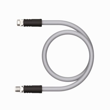
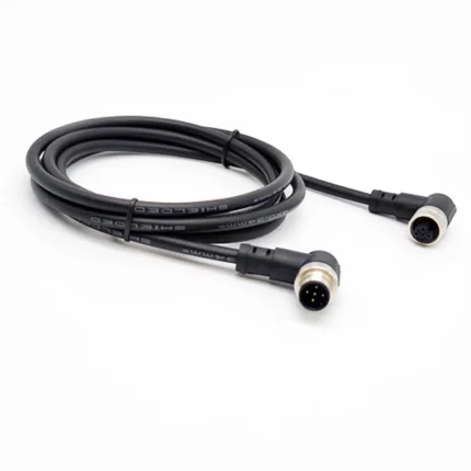
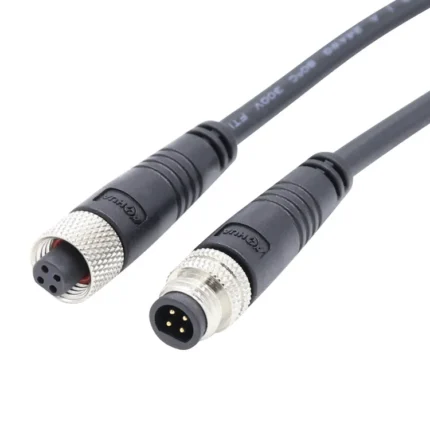
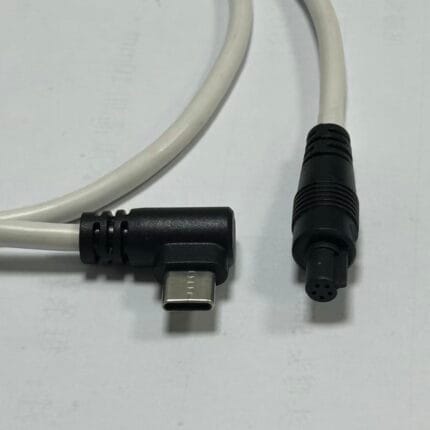
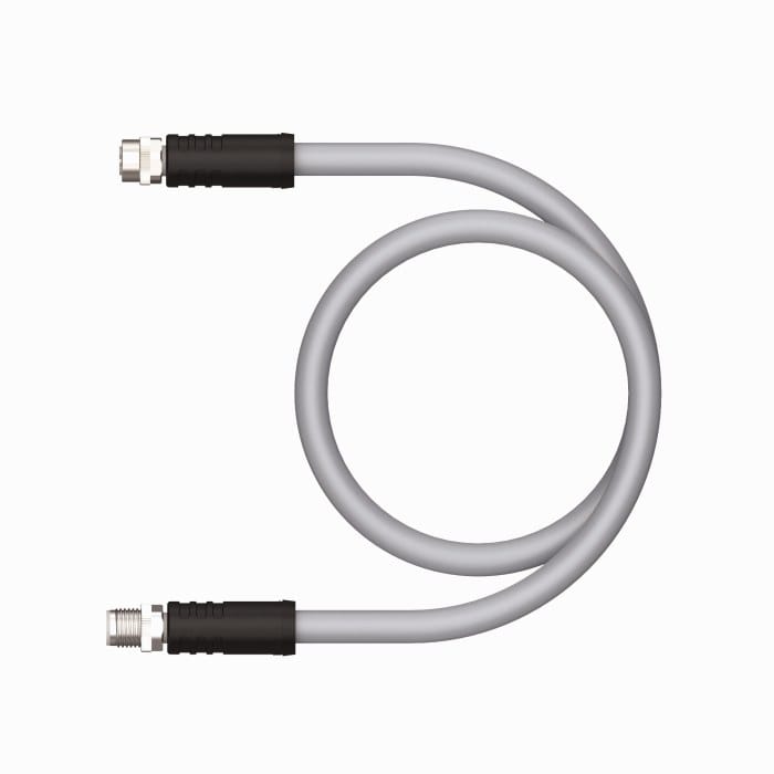
An M8 leak detection pigtail joins a sensing element or point sensor to the monitoring input in a liquid cooled rack. Slim, coolant compatible jacket, tight bend radius, flying lead or M8 end, built to your drawing.
Last updated: 13 September 2026
Overview
Liquid cooling moved from a niche to a default faster than the cabling around it did. A coolant distribution unit, a rack manifold and the quick couplings on a cold plate all need to know whether fluid is where it should be, and that means a sensing circuit that routes into places a normal cable will not go and survives sitting next to glycol or a dielectric fluid for years. This M8 leak detection pigtail is the short assembly that joins the sensing element or point sensor to the monitoring input.
Key Specifications
| Connector | M8 3-position, or 2-position variants, to flying leads |
|---|---|
| Function | Connection between leak sensing element or point sensor and monitoring input |
| Outer diameter | 3.5 to 4.5 mm class (pending supplier datasheet) |
| Minimum bend radius | 28 mm class (pending supplier datasheet) |
| Fluid compatibility | PG25 / LC25 glycol and dielectric coolant quoted in competitor data, pending immersion statement |
| Jacket fire rating | Plenum grade compound quoted in competitor data, pending confirmation of required rating |
| Standard lengths | 1 / 2 / 5 / 10 / 20 m |
| Termination | Flying lead, tinned or ferrule, to customer specification |
| Typical uses | CDU cabinets, rack manifolds, cold plate couplings, underfloor loops |
| Compliance files | RoHS and UKCA documentation being collected, no marking claim made until held |
What the pigtail actually does
Two things get confused in this category. A leak detection cable is the sensing element itself: a long run whose electrical behavior changes when fluid bridges it, which is also how the alarm is located along the run. A pigtail is not that. It is the connection between the sensing element or a point sensor and the monitoring input, and it has to be electrically boring: stable conductor resistance, a jacket that does not swell or leach into the coolant, and an outer diameter small enough to dress along a manifold. Most field problems with leak detection are not sensor failures, they are connection failures at this point.
Where the sensing points sit
Detection is only useful if it is placed where fluid actually escapes. This is the short list we see most often in a liquid cooled data hall.
| Location | What you are watching | Routing note |
|---|---|---|
| CDU cabinet floor | Pump seal leak and drain pan overflow | Dress to the low point, not to the cable tray |
| Rack manifold and blind-mate couplings | Weep at a coupling that has not fully seated | Keep the bend off the coupling body |
| Cold plate inlet and outlet | A quick coupling that has backed off a turn | Slim jacket, tight bend radius |
| Underfloor loop and containment | Fluid migrating away from the rack | Run the sensing element along the whole path |
| Heat exchanger and filter skid | Gasket seep during maintenance | Leave service length for filter changes |
M8 pigtail wiring
Three positions is the usual build: two for the sensing loop and one for the screen or a spare. Two-position variants exist where the sensor is a simple contact closure.
| Pin | Color | Function | Termination |
|---|---|---|---|
| 1 | Brown | Sensing loop A | Tinned, ferrule or to your specification |
| 2 | White | Sensing loop B | Tinned, ferrule or to your specification |
| 3 | Blue | Screen or spare conductor | Tinned, ferrule or to your specification |
The connector end is chosen to match the sensor or the controller you already have. If the monitoring panel is on an M12 interface, this is the family you are connecting into.
| Code | Contacts | Carries | Typical voltage | Relevance here |
|---|---|---|---|---|
| A | 3 to 12 | Sensor signals | 30-250 V | Most point sensors and controllers |
| D | 4 | 100 Mbit/s Ethernet | 60 V | Controller uplink, not the sensor |
| B | 4 to 5 | PROFIBUS-DP | 60 V | Rare in a data hall |
| C | 3 to 6 | AC power | 250 V AC | Pump and heater supplies |
| X | 8 | 10 Gbit/s Ethernet | 60 V DC | Not used for sensing |
| L | 4+FE | DC power | 63 V DC | CDU internal 24 V distribution |
| T | 2 to 4 | DC power | 63 V DC | Pump drives |
| K | 4+PE | Three-phase AC | 630 V AC | Pump motors |
| S | 2+PE / 3+PE | Single-phase AC | 630 V AC | Mains feed to the CDU |
| M | 5 to 6 | Servo power | 630 V AC | Not used here |
| P | 4 | EtherCAT P | 60 V | Not used here |
| Y | 8 (4+4) | Power plus data | 50 V | Not used here |
Fluid compatibility is the hard requirement
Coolant loops run on inhibited glycol mixtures, typically a propylene glycol blend of the PG25 or LC25 type, or on a dielectric fluid in direct-to-chip systems. A coolant that is harmless to mineral oil rated cable can soften, crack or leach plasticizer out of a jacket, and leached material ends up in a cold plate channel or a filter. Competitor data claims compatibility with both fluid families; that claim depends on the exact compound and the exact fluid, and it needs a supplier immersion statement before it goes into a data hall design.
Size and fire rating
Outer diameters in the 3.5 to 4.5 mm range and a minimum bend radius around 28 mm are quoted for comparable products. Those dimensions matter more than they look: a pigtail that will not turn the corner behind a manifold gets forced, and a forced cable lifts a coupling. Where the run leaves the rack for a plenum or a raised floor return, the jacket fire rating becomes a building requirement rather than a preference.
What we are confirming
Outer diameter, bend radius, conductor gauge, fluid compatibility and jacket fire rating for this range come from public competitor data, not a verified datasheet for our part. Lengths run from 1 to 20 m with a flying lead or a two or three position connector on the sensing end.
Typical applications for this M8 leak detection pigtail
- Coolant distribution unit cabinets and pump skids
- Rack manifolds and the blind-mate couplings at the rear of a rack
- Cold plate inlet and outlet couplings on GPU and CPU trays
- Underfloor loops and containment areas where a slim run is easier to dress
How to specify your build
- Connector – M8 3-position, 2-position, or flying lead both ends.
- Fluid – glycol blend or dielectric, and the product name.
- Length and the tightest bend the routing demands.
- Fire rating required for where the run leaves the rack.
- Termination – tinned, ferrule, or a specific contact.
- Quantity, prototype or production.
Workmanship and testing
Cable assemblies here are built to IPC/WHMA-A-620 Class 3 workmanship inside an ISO 9001 system, across a 32 to 12 AWG range. Continuity and pinout are verified on every unit before packing. Seal checking on the batch can be quoted when an ingress rating is specified.
Custom builds and ordering
Prototype quantity starts at 5 pcs with a 3 working day turnaround, and production starts at MOQ 500 pcs shipping 14 working days after approval. Where a new tool is needed, allow about 10 working days. We ship OEM and ODM builds under your part number and labeling, and can provide material certificates and first-article reports.
Related sensing and circular assemblies
- Leak Detection Harness for Data Center CDU and Rack Manifolds
- Liquid Leak Sensing Cable Pigtail for CDU and Rack Manifolds
- M8 3-Pin A-Coded Circular Connector Sensor / Actuator Cable
- M8 6-Pin A-Coded Right-Angle Sensor Cable
- M8 4-Pin A-Coded IP65 Waterproof Male-Female Power Cable
- M12 L-Code 16A Cable for IO-Link Power and AGV Drives
Full range: circular M8 and M12 cable assemblies.
Frequently Asked Questions
Is this the sensing cable itself?
No. The sensing cable is the element that changes behavior when fluid bridges it. The pigtail connects that element, or a point sensor, to the monitoring input.
Which fluids is the jacket compatible with?
Competitor data covers inhibited glycol blends and dielectric fluids. The claim depends on the exact compound and the exact fluid, so we ask for a supplier immersion statement before it goes into a design.
How slim can you build it?
Comparable products quote 3.5 to 4.5 mm outer diameter and around 28 mm minimum bend radius. Tell us the tightest bend in the routing and we will confirm what the jacket will take.
| Connector | M8 3-position, or 2-position variants, to flying leads |
|---|---|
| Function | Connection between leak sensing element or point sensor and monitoring input |
| Outer diameter | 3.5 to 4.5 mm class |
| Minimum bend radius | 28 mm class |
| Fluid compatibility | PG25 / LC25 glycol and dielectric coolant class |
| Jacket fire rating | Plenum grade compound |
| Standard lengths | 1 / 2 / 5 / 10 / 20 m |
| Termination | Flying lead, tinned or ferrule, to customer specification |
| Typical uses | CDU cabinets, rack manifolds, cold plate couplings, underfloor loops |
| Compliance files | RoHS and UKCA documentation being collected, no marking claim made until held |