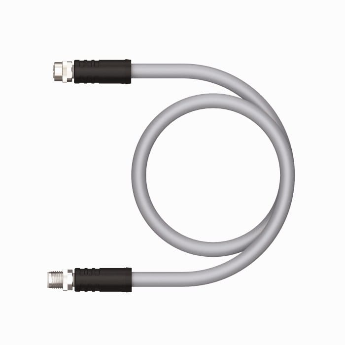
M12 M-Coded Motor Cable with Integrated Brake Conductors
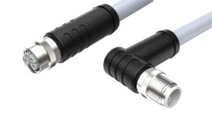
An M12 M-coded motor cable that puts the three motor phases, the protective earth and the DC brake pair into one M12 shell, removing a second connector from a compact servo or geared motor. Brake cores sized for release time, screen bonded to the shell.
Last updated: 13 September 2026
Overview
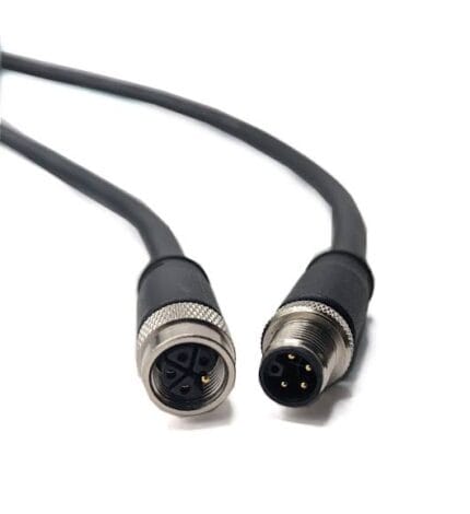
An M12 M-coded motor cable exists to remove one connector from a compact servo or geared motor. On a small three-phase motor with an integrated holding brake the usual arrangement is a power connector plus a second smaller connector for the brake winding: two cable entries, two gasketed joints, two part numbers to stock and two chances to mis-wire the machine. M-coding puts five power contacts and the protective earth into one M12 shell, so a single cordset carries the motor phases, the earth and the brake feed.
Key Specifications
| Connector series | M12, M-coded, 5 + PE (6 positions) |
|---|---|
| Coding standard | M12 power codings per IEC 61076-2-111 (confirm the applicable edition) |
| Typical supply | Three-phase AC motor feed with the DC brake pair in the same shell |
| Rated voltage | 600 V AC class – confirm against the build datasheet |
| Rated current | 8 A class – confirm against the build datasheet and test conditions |
| Conductor cross-section | 16 AWG class – exact size per order |
| Shielding | Braided screen bonded to the connector shell |
| Jacket | PUR for oil, coolant and flexing; PVC for fixed installation |
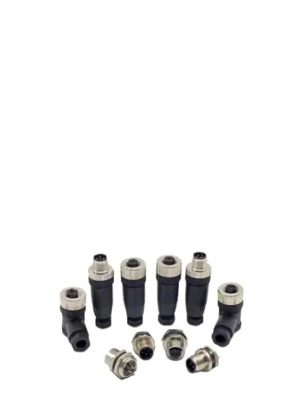
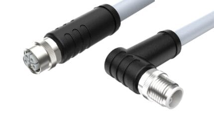
| Versions | Straight or right-angle, male or female, field-attachable screw or crimp |
| Typical loads | Servo and geared motors with holding brake, machine-mounted drives |
The brake pair is the part that gets undersized
On a brake motor the three phases are easy – they are sized the way any motor feed is sized. The brake winding is where builds go wrong. It is normally a DC load at 24 V, switched by a relay or a drive output, and the brake has to release within a stated time at the far end of the cable. That makes voltage drop over the run the binding constraint rather than the current rating of the contact. Give us the brake current, the release time and the length and we will size the pair rather than copy a catalog value.
The symptom of getting it wrong is unpleasant: the brake releases slowly or not at all, the drive faults on a following error, and the fault looks like a tuning problem. It is a cable sizing problem.
M-code contact reference
The six positions below are the arrangement for a brake-motor build. Where the motor has no brake, positions 4 and 5 are assigned per the drive maker’s drawing – confirm which you have before ordering, because the shell is identical either way.
| Position | Function | Note |
|---|---|---|
| 1 | U | Phase 1 |
| 2 | V | Phase 2 |
| 3 | W | Phase 3 |
| 4 | Brake + | DC brake winding, typically 24 V |
| 5 | Brake – | DC brake return |
| 6 | PE | Protective earth, first-make / last-break |
How M-code sits in the M12 coding family
M-code is the motor slot in the power group. Its neighbours are K-code for three-phase distribution, S-code for single-phase, and L and T for DC – and the keyway means none of them will accept each other’s plugs. The full map is below.
| Code | Positions | Carries | Typical use |
|---|---|---|---|
| A | 3 / 4 / 5 / 8 / 12 | DC sensor supply and signals, IO-Link | Proximity switches, photoelectric sensors, valve plugs |
| B | 5 | PROFIBUS-DP fieldbus | Legacy drives, remote I/O racks, weigh scales |
| C | 3 to 6 | AC power, dual keyway, extended earth | AC sensors, solenoid coils, legacy actuator blocks |
| D | 4 | 100 Mbit/s Ethernet over two pairs | PROFINET, EtherNet/IP, EtherCAT device drops |
| K | 4 + PE | Three-phase AC power | Motor feeds, power distribution blocks |
| L | 4 + PE | DC power | IO-Link power, AGV and drive supplies |
| M | 5 + PE | Three-phase motor plus brake pair | Servo and geared motors with holding brake |
| P | 4 + PE | Data pairs plus 24 V DC supply | Single-cable EtherCAT and remote I/O blocks |
| S | 3 + PE | Single-phase AC power | Field I/O blocks, cabinet heaters, pumps, fans |
| T | 4 | DC power, two circuits | Low-voltage DC distribution |
| X | 8 | Up to 10 Gbit/s Ethernet over four pairs | Machine vision, M12 to RJ45 10G links |
| Y | 6 + PE / 8 | Hybrid power plus Fast Ethernet | Valve islands, hybrid power and data drops |
A, B, C and D are defined in IEC 61076-2-101, X in IEC 61076-2-109 and the power codings K, L, M, S and T in IEC 61076-2-111 – confirm which edition your specification is written against. Y is a de-facto hybrid arrangement rather than an IEC-defined code. The 600 V and 8 A figures quoted above are the industry-standard class values for this coding; the values your assembly is built and verified to are the ones stated on your drawing.
What happens if the keyway is ignored
Every M12 connector shares the same thread, so from the outside a sensor lead and a mains motor feed look interchangeable. The internal key slot is what stops them being mated, and it is worth respecting: a signal cordset pushed into a motor outlet puts mains across contacts and insulation specified for a sensor circuit, and the failure is not intermittent – the insert fails, the device is damaged, and the earth path is usually the last thing to go. On a machine that mixes 24 V and mains, treat the coding as a safety feature rather than a catalog detail.
The servo motor end of the run is also where the screen earns its keep: inverter-borne noise couples into the brake and feedback circuits that share the same tray, so the braid is bonded to the connector shell rather than left to the cable gland.
Construction options
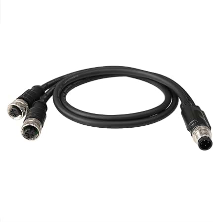
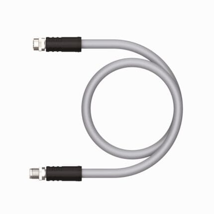
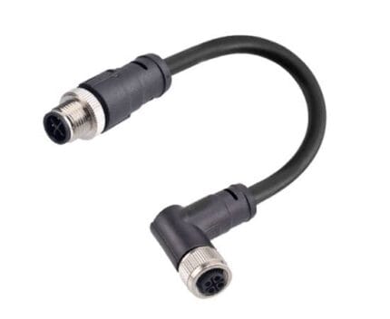
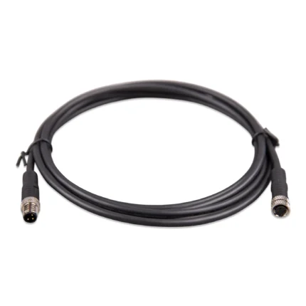
- Straight and right-angle overmolded cordsets, male and female
- Braided screen bonded to the connector shell for inverter noise
- PUR jacket where the run sees coolant, oil or continuous flexing; PVC for fixed installation
- Field-attachable screw or crimp versions so an installer can cut to length on site
- Made-to-order length with jacket printing on request
Typical applications for this M12 M-coded motor cable
- Compact servo and geared motors with an integrated holding brake
- Distributed machine-mounted drives on conveyor and packaging lines
- AGV and AMR traction motors where space behind the motor is tight
- Vertical axes where the brake is a safety function and release time matters
- Complete servo builds alongside our custom servo motor cable assembly and hybrid servo cable
- Three-phase distribution feeds using our M12 K-coded power cable
What we need from you
- Motor and drive model, or the pinout from the existing cable
- Brake voltage, current and required release time
- Run length, and whether the cable flexes
- Ambient temperature and anything the jacket is exposed to
- Straight or right-angle, and whether you need field-attachable ends
- Quantity, and whether a first article is required
Workmanship and testing
IPC/WHMA-A-620 Class 3 is the workmanship standard and ISO 9001 is the quality system behind it. We work from 32 to 12 AWG. Nothing ships without a continuity and pinout check, and seal checking can be added where an ingress rating is part of the specification.
Custom builds and ordering
Small runs start at 5 pcs and leave in 3 working days. At production volume the minimum is 500 pcs and lead time is 14 working days after approval. New tooling is about 10 working days on top. OEM and ODM orders ship under your part number, with material certificates and first-article reports available.
Related motor and M12 power assemblies
- M12 K-coded power cable for 630 V AC motor feeds
- M12 S-coded power cable for single-phase AC loads
- M12 L-code 16 A cable for DC power
- Encoder feedback cable with PUR jacket
- Custom servo motor cable assembly
- M12 drag chain cable for continuous flexing
Full range: Circular M8 and M12 cable assemblies.
Frequently Asked Questions
Can the brake pair share the cable with the motor phases?
Yes – that is the point of M-coding. The contacts are grouped so the brake circuit is kept away from the phase conductors and the screen stays continuous.
How do I size the brake conductors?
By voltage drop and release time, not by current rating. Give us the brake current, the required release time and the run length and we will size the pair.
Do I need a screened cable?
On an inverter-fed axis, yes. The braid bonded to the connector shell keeps switching noise off the brake and feedback circuits sharing the same tray.
Are field-attachable versions available?
Yes, in screw and crimp forms, so an installer can cut to length on site rather than carry a range of stock lengths.
| Connector series | M12, M-coded, 5 + PE (6 positions) |
|---|---|
| Coding standard | M12 power codings per IEC 61076-2-111 (confirm the applicable edition) |
| Typical supply | Three-phase AC motor feed with the DC brake pair in the same shell |
| Rated voltage | 600 V AC class – confirm against the build datasheet |
| Rated current | 8 A class – confirm against the build datasheet and test conditions |
| Conductor cross-section | 16 AWG class – exact size per order |
| Shielding | Braided screen bonded to the connector shell |
| Versions | Straight or right-angle, male or female, field-attachable screw or crimp |
| Typical loads | Servo and geared motors with holding brake, machine-mounted drives |
| Jacket | PUR for oil, coolant and flexing; PVC for fixed installation |