Type2 to NACS Adapter for Single-Phase AC Charging
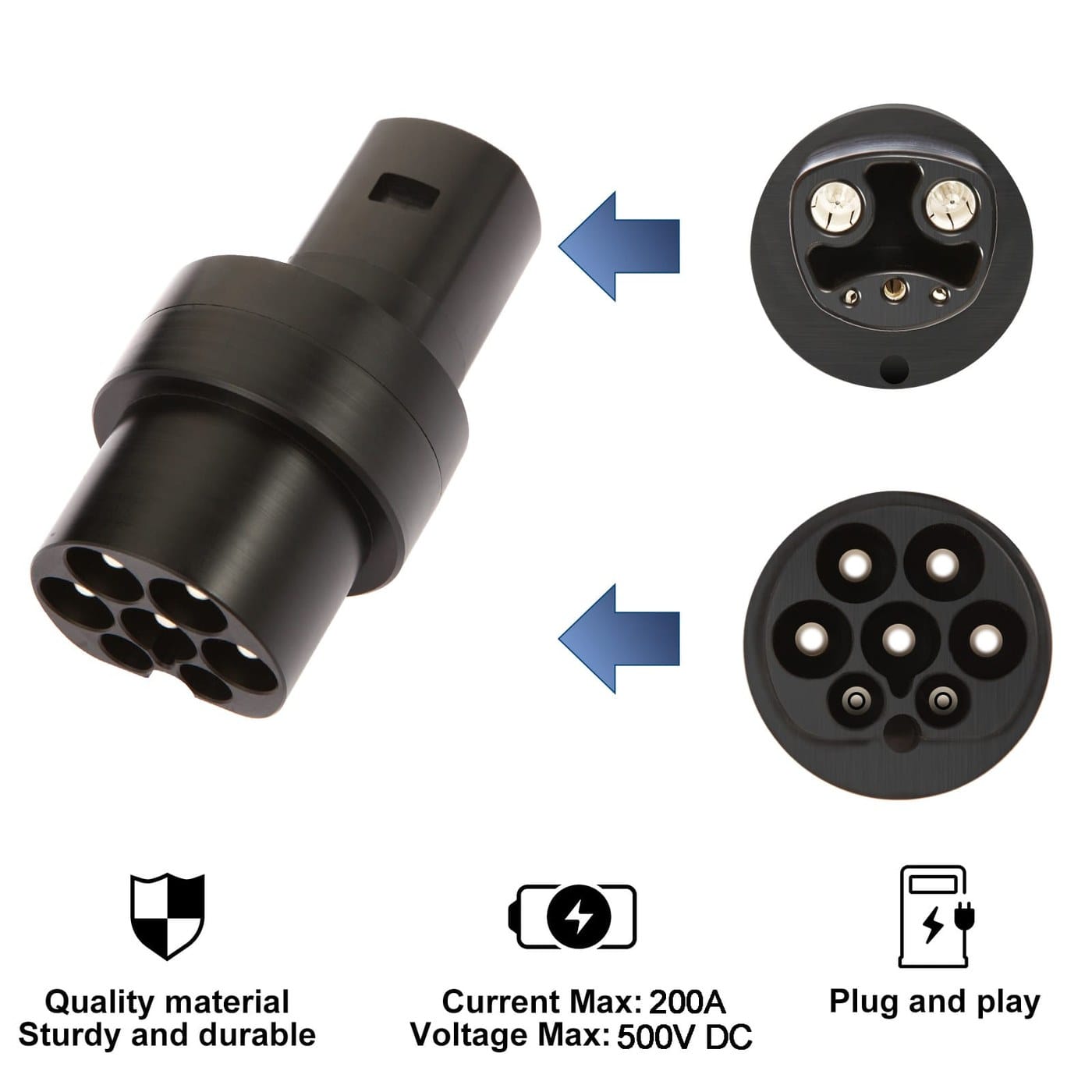
A Type2 to NACS adapter built for single-phase AC charging, joining an IEC 62196-2 Type 2 coupler to a connector made to the SAE J3400 interface. Passive, straight-through signaling, TPU jacket, built to the pinout and current on your drawing.
Last updated: 13 September 2026
Overview
A Type2 to NACS adapter joins a vehicle inlet built to one AC coupler
family to charge-point hardware built to the other. One end is an IEC 62196-2 Type 2 coupler,
the other is a connector built to the North American Charging Standard interface published as
SAE J3400. It carries single-phase AC and nothing else: it does not convert AC to DC, it does
not add current, and it does not turn a charge point into something it was not built to be. We
supply compatible components and build to the pinout, conductor size and length on your
drawing. We are not affiliated with any vehicle maker, and the interface names belong to their
respective owners.
Key Specifications
| Connector A | IEC 62196-2 Type 2 coupler |
|---|---|
| Connector B | NACS / SAE J3400 compatible connector, or J1772 in the reverse build |
| Rated current | 32 A single phase at 250 V AC; higher-current build on request |
| Conductor | 3 x 6 mm2 + 1 x 0.75 mm2, or 3 x 10 mm2 for the 40 A build |
| Cable length | 5 m standard |
| Jacket material | TPU, black, oil and salt resistant |
| Charging mode | Single-phase AC per IEC 61851 Mode 2 or Mode 3; no DC contacts populated |
| Signaling | Control pilot and proximity pilot passed straight through, no active electronics |
| Build direction | Type 2 to NACS as standard; NACS to J1772 reverse build on request |
| Sealing | Gasketed coupler bodies; mated ingress rating stated on your drawing |
Adapter, charging cable, and vehicle inlet are three different parts
Most of the confusion around this product comes from mixing up three things that sit in the same
photo. The inlet is the socket on the vehicle, the charging cable is the assembly with control
electronics at the wall end, and the adapter is a passive length of cable with a coupler at each
end. Separate those three and the questions get easy.
| Part | Where it lives | What it does | What it cannot do |
|---|---|---|---|
| Vehicle inlet | Built into the car | Receives the coupler and carries the charging current into the onboard charger | Change the current or voltage the car will accept |
| Charging cable / EVSE lead | Wallbox or charge post | Supplies current and runs the control pilot negotiation with the vehicle | Charge a vehicle whose inlet does not match its coupler |
| Adapter (this product) | Between the two | Bridges two coupler families mechanically and electrically | Convert AC to DC, or raise the current either end allows |
The session always runs at the lower of the two limits. If the charge point offers one current
level and the vehicle accepts another, you get the smaller value, and that is correct behavior
rather than a defect.
Single-phase AC: what each Type 2 contact does
IEC 62196-2 gives the Type 2 interface seven contact positions. Three of them are always the
same, and the other four are allocated according to the operating mode. In single-phase AC
charging, four of the seven carry the work.
| Contact | Name | Function | Used in single-phase AC |
|---|---|---|---|
| PP | Proximity pilot | Pre-insertion signaling; a resistor between PP and PE codes the current capability of the cable | Yes |
| CP | Control pilot | Post-insertion signaling; a 1 kHz PWM signal advertises the available current | Yes |
| PE | Protective earth | Full-current protective earthing conductor | Yes |
| N | Neutral | Return conductor for single-phase AC | Yes |
| L1 | Line 1 | The single phase conductor | Yes |
| L2 | Line 2 | Second phase | No, three-phase only |
| L3 | Line 3 | Third phase | No, three-phase only |
The Type
2 connector family is defined in IEC 62196-2 and, in its AC signaling, follows the same
control pilot and proximity pilot logic described in SAE J1772 and IEC 61851-1. That shared
signaling is why a passive adapter can work at all: both ends are already speaking the same
analog language, so nothing has to be translated.
Why this build is single phase only
A single-phase AC adapter carries one phase, the neutral, protective earth and the two
signaling contacts. Three-phase AC is a different cable with three phase conductors. DC charging
is different again: sessions run at currents where every extra contact set is a thermal risk, and
the signaling is digital rather than PWM. Our build does not populate DC contacts.
Construction
- Conductors: 3 x 6 mm2 power plus 1 x 0.75 mm2 signal as standard; 3 x 10 mm2 for the
higher-current build. - Jacket: TPU in black, chosen for oil, road salt and the abrasion of being dragged across a
driveway or a workshop floor. - Length: 5 m standard, other lengths to order.
- Molded coupler bodies with integrated strain relief, and a cap for the vehicle-side
connector. - Signaling contacts wired straight through, so the station and the vehicle still negotiate
directly.
Inspection and care
An adapter adds one contact set to a high-current path, so inspect the coupling faces before
every session: pitting, discoloration, a loose fit, or a latch that no longer holds. Seat each connector until it latches and
let the cable hang from its own strain relief. Store it coiled off the ground with the caps on.
Do not use one that has been run over, cut or crushed, and do not use one to extend a lead that
is already at its limit.
How to specify your build
- Inlet and socket — which coupler is on the vehicle and which is on the
charge point you need to reach. - Current and conductor size — 32 A as standard, or state the figure you
need. - Length, and whether it is a driveway, depot or worksite run.
- Direction — Type 2 to NACS, or the NACS to J1772 reverse build.
- Quantity, and whether this is a sample or a production order.
Typical applications for this Type2 to NACS adapter
- Fleet depots where the charge posts and the vehicles were bought to different standards
- Home and workplace charging where the wallbox lead is fixed and the vehicle inlet changed
- Worksite and temporary charging where a generator-fed station meets mixed vehicle types
- Vehicle preparation and logistics yards alongside our V2L
discharge adapter cable from Type 2 inlet to AC sockets - Distributor programs that need a private-labeled adapter with their own part number
Workmanship and testing
Our line is ISO 9001 certified and every assembly is built to IPC/WHMA-A-620 Class 3 workmanship across 32 to 12 AWG. Continuity and pinout are checked on every unit before packing, and seal checking can be quoted where an ingress rating is specified.
Custom builds and ordering
Prototypes are quoted from 5 pcs and ship within 3 working days. Volume production starts at 500 pcs with a 14 working day lead time after approval, and about 10 working days more when a new tool is needed. Private labeling carries your part number, and material certificates with first-article reports are available on request.
Related assemblies
- V2L Discharge Adapter
Cable from Type 2 Inlet to AC Sockets - M12 S-Coded Power Cable
for Single-Phase AC Loads - Battery
Cable Installation Kit with Terminal Clamps and Lugs - Heavy-Duty
Battery Power Cable with Ring Terminals - EV High Voltage Harness
Built to Print for the vehicle-side build
Full ranges: automotive
cable and wire harness and custom
wire harnesses.
Frequently Asked Questions
Will this adapter let me use a DC fast charger?
No. It is a single-phase AC build with no DC contacts populated. DC charging runs a digital
signaling session at currents where a passive adapter is the wrong component.
Does the adapter change the charging speed?
No. The station and the vehicle still negotiate between themselves, and the session runs at
the lower of the two limits. An adapter cannot raise what either end is willing to deliver.
Can I have the reverse direction?
Yes. The NACS to J1772 direction is built to order on the same mechanical platform. State the
direction you need when you send the drawing.
What length should I order?
5 m is the standard build. Shorter runs suit a wall-mounted post in a garage; longer runs
suit a depot where the post sits behind a vehicle. Length affects voltage drop, so tell us the
run and the current together.
How is the current rating established?
The rating your unit is built and verified to is the one on your order.
| Connector A | IEC 62196-2 Type 2 coupler |
|---|---|
| Connector B | NACS / SAE J3400 compatible connector, or J1772 in the reverse build |
| Rated current | 32 A single phase at 250 V AC; higher-current build on request |
| Conductor | 3 x 6 mm2 + 1 x 0.75 mm2, or 3 x 10 mm2 for the 40 A build |
| Cable length | 5 m standard |
| Jacket material | TPU, black, oil and salt resistant |
| Charging mode | Single-phase AC per IEC 61851 Mode 2 or Mode 3; no DC contacts populated |
| Signaling | Control pilot and proximity pilot passed straight through, no active electronics |
| Build direction | Type 2 to NACS as standard; NACS to J1772 reverse build on request |
| Sealing | Gasketed coupler bodies; mated ingress rating stated on your drawing |