Liquid Leak Sensing Cable Pigtail for CDU and Rack Manifolds
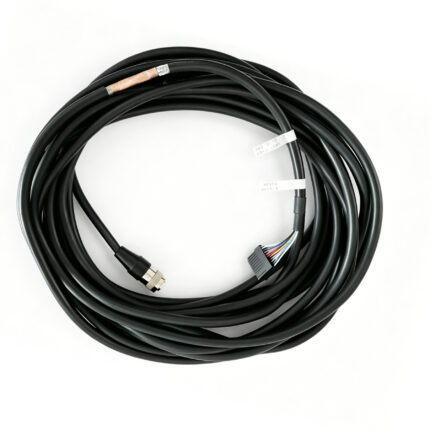
A liquid leak sensing cable pigtail that connects the sensing element in a coolant distribution unit or rack manifold to the controller input. 2-pin or M8 3-pin to flying leads, cut to the route you draw, 1 m to 20 m. Tell us the input type and we build to it.
Last updated: 13 September 2026
Overview
A liquid leak sensing cable assembly is rarely the part anyone blames when a rack floods, and it is almost always the part that decides whether anyone found out in time. The sensing element and the detection electronics are supplied by others; what this product is, is the short pigtail between them – the piece that has to survive the route along a manifold, under a cold plate and past the quick connects, and still present the right electrical signature to the controller input.
Key Specifications
| Product type | Leak detection sensing cable pigtail |
|---|---|
| Connector | 2-pin or M8 3-pin to flying leads |
| Outside diameter | 3.5 mm to 4.5 mm – to be confirmed |
| Minimum bend radius | 28 mm – design target, to be confirmed |
| Length options | 1 / 2 / 5 / 10 / 20 m, cut to the drawn route |
| Fluid exposure | Glycol and dielectric coolant – compatibility to be confirmed |
| Controller inputs | Resistive loop, contact closure or voltage – set per controller |
| Jacket rating | Flame rating to be confirmed by listing, not by compound name |
| Labeling | Both ends labeled to your tag scheme |
Routing decides whether the system detects anything
The most common failure in a coolant distribution unit or a rack manifold installation has nothing to do with the cable. A sensing element that is not in the drip path stays dry while the rack floods. Before you pick a length, walk the route: the element runs along the manifold and under the cold plate quick connects, which is exactly where a leak appears, and the pigtail has to reach the controller without crossing the power distribution in the rack.
| Route position | Why it is chosen | What usually goes wrong |
|---|---|---|
| Along the manifold underside | Gravity puts the first droplets here | Cable clipped to the top of the pipe and never wetted |
| Under quick connects | The highest probability leak point in the loop | Element routed behind the drip, shielded by the fitting body |
| Across the rack floor or drip tray | Catches everything that escapes above | Trays cleaned out and the element lifted or unclipped |
| At the CDU pump base | Seal weep collects before it spreads | No route planned, element added after commissioning |
What kills the pigtail itself
Once the route is right, the assembly still has to live in it. These are the mechanisms we design against:
- Coolant contact over time – jacket compound has to be checked against the specific fluid the customer runs, including long-term immersion at temperature, not against a generic “coolant resistant” claim.
- Tight bends at the manifold – a 28 mm target bend radius is easy to draw and easy to violate with a zip tie; the fixing method matters as much as the cable.
- Wrong controller input – resistive loop, contact closure and voltage inputs each need a different lead-out and often a different connector.
- Power running alongside – a sensing loop routed next to the rack power distribution picks up noise and reports alarms that are not there.
- Unlabeled ends – in a rack with eight identical pigtails, the second service call always starts with identification.
Pick the input before you pick the connector
This is the single most common reason these assemblies get returned. Three input families cover most of the market and they are not interchangeable at the lead-out:
| Controller input | What the lead-out has to present | Typical connector |
|---|---|---|
| Resistive loop | Defined loop resistance, stable across the run length | 2-pin, or M8 3-pin where a sealed shell is needed |
| Contact closure | Clean make or break, no meaningful loop resistance | 2-pin, flying leads for screw terminals |
| Voltage or analog | Screened lead-out, low leakage, stable reference | M8 3-pin with shield carried to the shell |
Confirm which one your controller expects before ordering. If you are not sure, send the controller model and we will read the input off the manual.
Figures still pending confirmation
The flame rating, the minimum bend radius, the diameter range and the fluid compatibility statement in the table all come from competitor and application literature, and each is on the confirmation list. Any plenum classification has to be backed by an actual listing rather than by a compound trade name, and the jacket has to be checked against the coolant the customer actually runs. We would rather leave a cell marked pending than print a number we cannot reproduce.
Typical applications for this liquid leak sensing cable
- Coolant distribution units in high-density compute racks, with our M8 leak detection pigtail where a sealed shell is required
- Rack manifold and cold plate runs on direct-to-chip liquid cooling loops
- Multi-rack installations wired back to a common controller, built up as a leak detection harness
- Retrofit sensing on existing manifolds where the route is already fixed
- Skid and cabinet builds where the sensing element and the controller are supplied separately
Installation notes
Keep the pigtail away from the power distribution in the rack, label both ends, and confirm the controller input type before ordering. Do not coil the surplus length beside the manifold: a loop of cable collects condensate and reports a leak that is not in the loop. We cut to the route you draw so there is no surplus to coil.
Workmanship and testing
Every build is assembled and inspected to IPC/WHMA-A-620 Class 3 workmanship under our ISO 9001 system. We terminate conductors from 32 to 12 AWG. Each unit is checked for continuity and pinout before packing, and where the build carries an ingress rating we can add seal checking on the production run.
Custom builds and ordering
Prototypes run from 5 pcs with a 3 working day turnaround; volume orders start at MOQ 500 pcs and ship 14 working days after sample sign-off. If the build needs tooling we do not already hold, add roughly 10 working days. OEM and ODM orders ship under your part number and labeling, and material certificates and first-article reports are available on request.
Related assemblies
- M8 Leak Detection Pigtail for CDU and Manifold Sensing
- Leak Detection Harness for Data Center CDU and Rack Manifolds
- IP68 Industrial Data Cable for Serial, USB and Ethernet Ports
- IP67 2-Pin Waterproof Connector Cable
- Custom Shielded Ethernet Data Cable
Full range: signal and data cables.
Frequently Asked Questions
Do you supply the sensing element and the controller?
No. Those come from the detection specialist. We build the pigtail between them, cut to the route you draw and terminated to the input your controller expects.
Which connector do I need?
2-pin to flying leads suits screw terminal inputs. M8 3-pin suits a sealed shell at the manifold, and it also gives you somewhere to land the screen on voltage or analog inputs.
Can I get lengths between the standard ones?
Yes. The listed lengths are what most racks use; we cut to the route on the drawing, so an odd length costs nothing extra and removes the surplus you would otherwise coil.
What is the minimum order?
Five pieces is the prototype minimum and those ship in 3 working days. Production quantities start at 500 pcs, 14 working days after sample approval.
| Product type | Leak detection sensing cable pigtail |
|---|---|
| Connector | 2-pin or M8 3-pin to flying leads |
| Outside diameter | 3.5 mm to 4.5 mm – to be confirmed |
| Minimum bend radius | 28 mm – design target, to be confirmed |
| Length options | 1 / 2 / 5 / 10 / 20 m, cut to the drawn route |
| Fluid exposure | Glycol and dielectric coolant – compatibility to be confirmed |
| Jacket rating | Flame rating to be confirmed by listing, not by compound name |
| Controller inputs | Resistive loop, contact closure or voltage – set per controller |
| Labeling | Both ends labeled to your tag scheme |