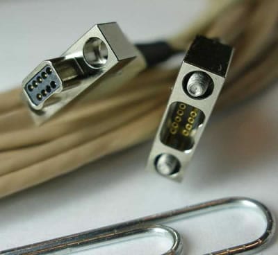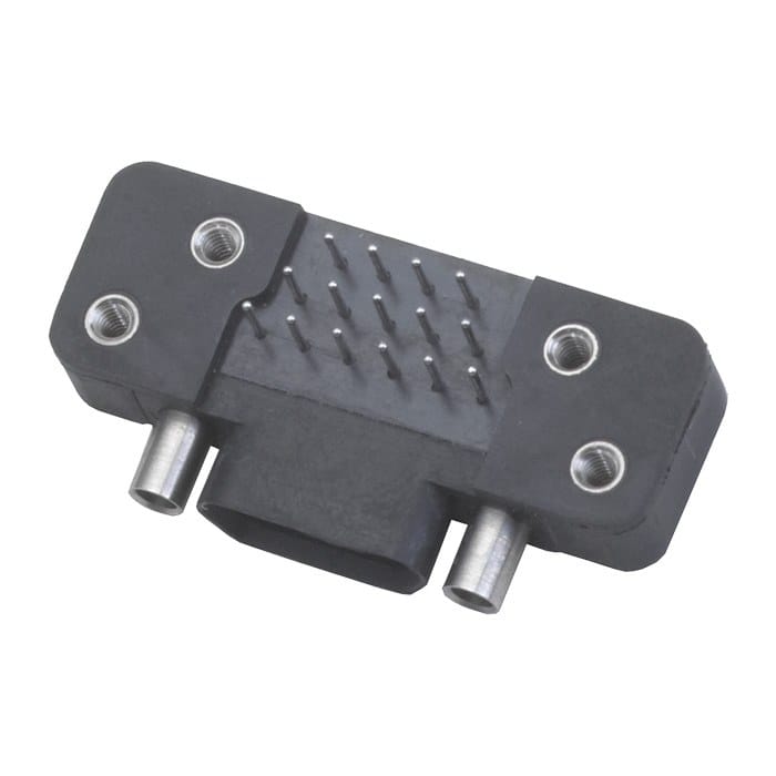
Micro-D Shielded Jumper with Twisted Pair and Coax Mix for Avionics
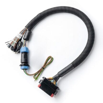
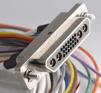
A Micro-D shielded jumper built to print, mixing shielded twisted pair, coax and discrete signal legs in one branch at 0.05 inch pitch. Each screen is terminated on its own path at the backshell. Send the pinout, or send the original jumper and we will measure it.
Last updated: 13 September 2026
Overview
A Micro-D shielded jumper exists because a panel ran out of room. The 0.05 inch contact pitch puts a large number of circuits into a shell that still survives vibration, which is why these connectors turn up on guidance sections, line replaceable units, gimbals and instrumentation pods. The consequence for the harness is unforgiving: at that pitch there is no room to correct a mistake at the backshell, and a mixed build carrying coax, twisted pair and discrete wires in one branch brings three different shield treatments together in a few square centimeters. We build to your print, and we resolve those three treatments before a single contact is loaded.
Key Specifications
| Build Type | Build to print or build to sample |
|---|---|
| Connector Style | Micro-D twisted-pin contacts, 0.05 inch pitch |
| Shell | Metal or plastic shell per drawing |
| Positions | 9 to 100 positions |
| Wire | ETFE insulated 26 AWG, M22759/33 style or nominated equivalent |
| Leg Types | Shielded twisted pair, coax and discrete signal in one branch |
| Color Coding | MIL-STD-681 practice when specified |
| Testing | Continuity, dielectric withstand, screen continuity, dimensional check |
Why 0.05 inch pitch changes the build
This connector family is part of the wider D-subminiature group, shrunk to roughly half the contact spacing of a standard density shell. Two practical consequences follow. First, the contacts are twisted-pin rather than simple stamped pins, so each one presents multiple contact points and tolerates vibration far better than the size suggests. Second, serviceability drops sharply: you cannot comfortably re-work a termination under a microscope at this pitch with a full bundle in the way, so the assembly order matters. We load, pot and close in the sequence the connector design requires, and we record it against the serial number.
A mixed jumper is really three different cables that happen to share a connector. Each leg wants something different:
| Leg type | What it usually carries | How the screen is handled | Where it goes wrong |
|---|---|---|---|
| Shielded twisted pair | Differential data, serial links, low level analog | Screen landed on its own drain, kept short, never shared with another leg | Two pairs sharing one drain path, which couples them to each other |
| Coax | Video, RF, timing and reference signals | Impedance held to the contact, screen terminated at the contact interface | Coax dressed around a corner tighter than the cable allows, changing the impedance at the bend |
| Discrete signal | Power, discrete IO and sense lines | Usually unshielded and routed away from the pair and coax bundles | Discretes run alongside a pair and coupling into it |
| Mixed in one branch | All of the above inside one overbraid | Each screen terminated separately at the backshell, then the overall braid | Every screen gathered into a single pigtail |
The last row is the one we ask about first. Gathering every screen into a single pigtail is fast, and it is the most common reason a jumper passes continuity and then fails on the bench.
Screen separation on a mixed build
A shielded jumper performs as well as its termination, not as well as its cable. Where a mixed build carries coax and twisted pair in the same branch, we agree the screen treatment for each leg before the build starts, land each screen on a full circumferential interface at the backshell, and keep the drain path as short as the geometry allows. If your design calls for a particular leg to be left floating at one end, say so on the drawing. That is a decision for your engineering team and we will build exactly to it, but we will not make it for you silently.
The fastest way to lose a week on a jumper order is a print that is missing one line. This is the list we check against:
| Item on the drawing | Why we need it | What happens when it is missing |
|---|---|---|
| Pinout table | Everything else depends on it | We cannot start; a mating face photograph is the fallback |
| Contact arrangement and shell size | Decides the backshell and the tooling | A backshell that will not close over the finished bundle |
| Leg type per position | Decides the screen treatment for each leg | Screens get grouped by default and performance suffers |
| Conductor gauge and insulation per leg | Coax and discrete legs rarely use the same wire | The wrong wire on a coax leg, or a bundle too thick for the shell |
| Branch lengths and breakout positions | At this pitch there is no slack to absorb an error | A branch that will not reach, or a bulge at the backshell |
| Screen termination instruction | Full circumferential, or a stated exception | We stop and ask, and the build waits |
Length, breakouts and the retrofit problem
Standard jumper lengths suit a bench, and a rack installation rarely agrees with them. We cut to the exact length on the drawing and position breakouts where the mechanical model says they belong. For a like for like replacement, send the original jumper and we will measure it rather than trust a part number, because two part numbers that look identical often differ in breakout position by enough to matter at this scale.
Typical applications for this Micro-D shielded jumper
- Avionics line replaceable units and instrument pods
- Gimbal, turret and payload wiring
- Downhole and borehole instrumentation strings
- Test racks and engineering bench harnesses
- Small satellite and launch vehicle internal links
Inspection before release
- Continuity and polarity on every position
- Dielectric withstand test at the voltage stated on the drawing
- Screen continuity and drain termination inspection
- Dimensional check of overall length and breakout positions
Workmanship and ordering
Each assembly is built and inspected to IPC/WHMA-A-620 Class 3 criteria within an ISO 9001 quality system, covering 32 to 12 AWG. Continuity and pinout are tested on every unit before packing. Where the specification calls for an ingress rating, seal checking on the batch can be quoted.
Five pieces is where a prototype starts and it ships in 3 working days. Production requires 500 pcs minimum and takes 14 working days after approval. Non-stock tooling adds around 10 working days. Private-label builds ship under your part number and labeling; material certificates and first-article reports are available on request.
Frequently Asked Questions
Can you mix coax, twisted pair and power in one shell?
Yes, provided the contact arrangement supports it. Send the arrangement and we will confirm which contact sizes are available for each leg before quoting.
What is the smallest prototype quantity?
For prototypes the floor is 5 pcs and lead time is 3 working days. Production orders begin at 500 pcs and ship 14 working days after sample sign-off.
Can you identify a connector from a photograph?
Often. A clear photo of the mating face gives us the shell size, the arrangement and the gender, and we confirm it with you before quoting.
Do you terminate both ends?
Yes. Micro-D to Micro-D, Micro-D to a different connector family, or Micro-D to flying leads, in straight or right-angle bodies.
Related assemblies
- MIL-DTL-83513 Micro-D and MIL-DTL-32139 Nano-D Cable
- Nano-D Space Harness Built to Drawing for CubeSat Internal Wiring
- Lightweight UAV Wire Harness for eVTOL Propulsion and Avionics Bays
- 38999 High Speed Harness with Overmolded Strain Relief for 10GbE Links
- MIL-DTL-38999 Series III Military Circular Cable Assembly
- Rugged RJ45 IP68 Military Ethernet Cable
Full range: Custom Wire Harnesses.
| Build Type | Build to print or build to sample |
|---|---|
| Connector Style | Micro-D twisted-pin contacts, 0.05 inch pitch |
| Shell | Metal or plastic shell per drawing |
| Positions | 9 to 100 positions |
| Wire | ETFE insulated 26 AWG, M22759/33 style or nominated equivalent |
| Leg Types | Shielded twisted pair, coax and discrete signal in one branch |
| Testing | Continuity, dielectric withstand, screen continuity, dimensional check |
| Color Coding | MIL-STD-681 practice when specified |