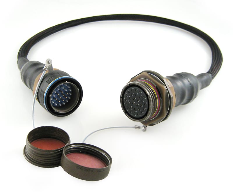
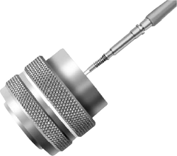
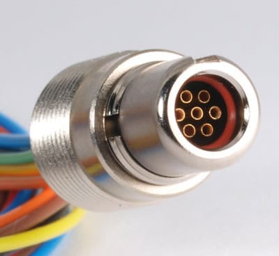
MIL-DTL-38999 Series III Military Circular Cable Assembly
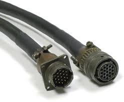
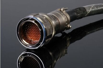
A military mil dtl cable built around MIL-DTL-38999 Series III threaded circular connectors, shell sizes 09 to 25, wired to the insert arrangement you name. Shielded bundle, PUR or FEP jacket, strain-relieved backshell boots.
Overview
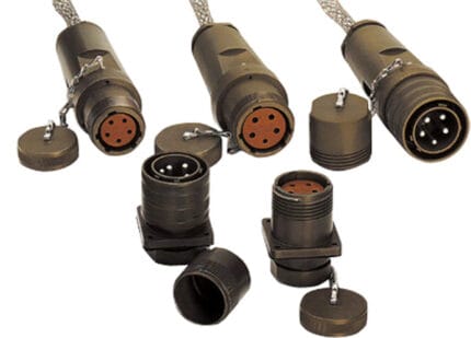
A military mil dtl cable built on MIL-DTL-38999 Series III is the default answer when a harness has to survive vibration, salt air and a wide temperature swing and still be serviceable in the field. It belongs to the circular connector family specified for exactly that job. Series III is the threaded member of the family: a tri-start coupling that pulls the two halves together and locks, with scoop-proof shells so a pin cannot be bent by a plug that is offered up slightly off axis. Shell sizes run from 09 to 25, insert arrangements are selected from MIL-STD-1560, and we wire to the arrangement you name rather than to a house standard. We build and verify to your drawing; we do not claim certification to the detail specification.
Key Specifications
| Connector Family | MIL-DTL-38999 Series III |
|---|---|
| Shell Sizes | 09, 11, 13, 15, 17, 19, 21, 23, 25 |
| Contact Layouts | Per MIL-STD-1560; 3 to 128 contacts |
| Shell Material | Aluminum alloy, olive drab cadmium or zinc-cobalt |
| Contact Material | Copper alloy, gold plating 1.27 micron typical |
| Operating Temperature | -65 C to +200 C |
| Sealing | IP67 mated |
| Length | OEM build to required length |
Four series, one part number prefix: which one is on the drawing?
MIL-DTL-38999 is a family rather than a part, and the series letter changes the coupling, the silhouette and, in practice, whether it will mate with the receptacle already fitted to your box. Series III is the one most new designs specify, largely because the threaded coupling gives both a positive lock and a low-resistance shell-to-shell path for EMI grounding.
| Series | Coupling | What that buys you | What to watch |
|---|---|---|---|
| Series I | Bayonet | Fast, quarter-turn connect and disconnect | Bayonet coupling can loosen under sustained vibration if the springs age |
| Series II | Low-silhouette bayonet | Same action in a shorter shell | Lower contact counts than the same shell size in Series I |
| Series III | Tri-start threaded, self-locking | Positive lock, scoop-proof, best EMI shell path | Takes longer to couple; needs the right wrench or a good grip |
| Series IV | Breech coupling | Quick disconnect without a full thread turn | Least common in general harness work; confirm availability before you design it in |
Reading the callout before you send it to us
Most RFQs for this family arrive as a part number rather than a description, which is good, because the number encodes everything we need. If you only have a NSN or a drawing, the fields below are the ones we will ask you for. Where a field is unclear we will come back to you rather than guess, because an alternate keying position is invisible until two halves will not mate.
| Field in the callout | What it fixes | What goes wrong if it is wrong |
|---|---|---|
| Series | Coupling style and shell geometry | The plug will not couple at all |
| Shell style | Straight plug, wall-mount receptacle, jam-nut, box mount | Right connector, wrong mounting hardware |
| Shell size | Physical size and the range of available arrangements | Too large to fit, or too small for the arrangement |
| Insert arrangement | Contact count, size and position per MIL-STD-1560 | Correct shell, wrong pin pattern |
| Contact style and gender | Pin or socket, crimp or solder, signal or coax or power | Mating halves that are both pins |
| Alternate keying position | Polarization, so adjacent connectors cannot be swapped | Two identical connectors get cross-connected in service |
What the environmental clauses actually ask for
The reason this family costs what it costs is not the contacts, it is the qualification: salt spray, vibration, shock and thermal cycling, plus shell-to-shell conductivity and EMI shielding effectiveness. Those are real requirements with real test methods behind them, and they belong on your drawing rather than in a marketing sentence. Tell us the exposure hours, the vibration profile and the temperature range you need met, and we will tell you honestly which of them we can verify in house and which need an external laboratory.
- Salt spray – the exposure hours and the plating system go together; a zinc-cobalt or zinc-nickel shell and a cadmium shell do not behave the same way in a Fog chamber.
- Vibration – the profile matters more than the number. Random and sinusoidal profiles expose different weaknesses.
- Thermal cycling – the extremes plus the dwell time, because it is the cycling that loosens a contact rather than the temperature itself.
- Sealing – mated ingress rating plus whether the backshell and the jacket are part of the sealed path.
Construction
- Series III shells in the size and plating you nominate, with the keying position on the drawing.
- Contacts crimped on the correct die for the size, inserted and removed only with the proper tool.
- Shielded bundle with the braid terminated 360 degrees into the backshell, not pigtailed.
- PUR or FEP jacket depending on the temperature and fluid exposure.
- Overmolded or heat-shrunk backshell boots with strain relief tied into the shell.
What we need from you to quote
- The full connector callout for both ends, including keying and plating.
- The insert arrangement per MIL-STD-1560, and which cavities are populated.
- The pinout, or the schematic the harness has to match.
- Jacket and shielding, with the temperature and fluid exposure.
- Length and quantity, plus whether this is a prototype or a production order.
Typical applications for this military mil dtl cable
- Avionics and ground support equipment where a threaded, EMI-grounded coupling is mandatory
- Radar, radio and shelter interconnects, alongside a 38999 high-speed harness
- Vehicle and shipboard harnesses exposed to salt air, paired with a MIL-DTL-5015 circular power assembly
- Test and measurement racks that have to survive a transport case, next to a railway rolling stock harness
- Unmanned platforms where weight and vibration both matter, with a lightweight UAV wire harness on the airframe side
Workmanship and testing
MIL-DTL-38999 Series III Military builds are made to IPC/WHMA-A-620 Class 3 workmanship inside an ISO 9001 system, over a 32 to 12 AWG range. continuity and pinout are verified on each MIL-DTL-38999 assembly before packing, and seal checking is quoted whenever an ingress rating is on the drawing.
Material declarations against RoHS and REACH are issued per project, alongside the dimensional and electrical reports agreed at quotation; see certifications, compliance and material declarations. Where your drawing names a UL style or another approval, the build follows your drawing and ships with the supporting document rather than a claim of our own. Overmold tooling for this part is designed and cut in our own tool room under in-house mold making and overmold tooling, so the tool belongs to your program and a revision is a machining job rather than a new negotiation. Related reading: how we build and document first articles.
Custom builds and ordering
For MIL-DTL-38999 Series III Military builds, prototypes run from 1 to 50 pcs with a 3 working day turnaround. Volume orders begin at 500 pcs and ship 14 working days after approval. Tooling not already held adds around 10 working days. OEM and ODM MIL-DTL-38999 work ships under your part number and labeling, and material certificates plus first-article reports are available.
Related military harnesses
- 38999 High-Speed Harness for Radar and Airborne Ethernet
- MIL-DTL-5015 Circular Power Cable Assembly
- Micro-D Shielded Jumper, MIL-DTL-83513
- Lightweight UAV Wire Harness
- Railway Rolling Stock Harness
Full range: custom wire harnesses.
Frequently Asked Questions
Are you certified to MIL-DTL-38999?
MIL-DTL-38999 Series III Military builds are made to IPC/WHMA-A-620 Class 3 workmanship inside an ISO 9001 system, over a 32 to 12 AWG range. continuity and pinout are verified on each MIL-DTL-38999 assembly before packing, and seal checking is quoted whenever an ingress rating is on the drawing.
Will Series III mate with Series I?
No. Different coupling and different shell geometry. The series letter is the first thing to check on the callout.
Why is keying position worth specifying?
Because two otherwise identical connectors next to each other on a panel are a cross-connection waiting to happen. Alternate keying makes the wrong one physically impossible to plug in.
Can you terminate coax and power contacts in the same shell?
Yes, where the insert arrangement allows it. Send the arrangement number and which cavities take which contact type.
| Connector Family | MIL-DTL-38999 Series III |
|---|---|
| Shell Sizes | 09, 11, 13, 15, 17, 19, 21, 23, 25 |
| Contact Layouts | Per MIL-STD-1560; 3 to 128 contacts |
| Shell Material | Aluminum alloy, olive drab cadmium or zinc-cobalt |
| Contact Material | Copper alloy, gold plating 1.27 micron typical |
| Operating Temperature | -65 C to +200 C |
| Sealing | IP67 mated |
| Length | OEM build to required length |