MIL-DTL-5015 Circular Power Cable Assembly
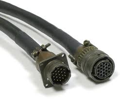
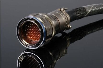
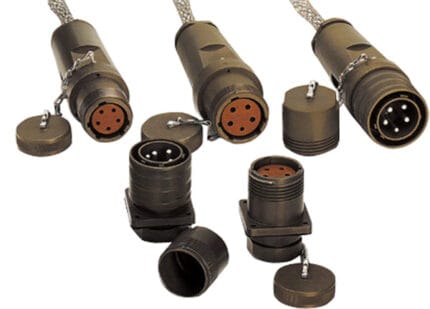
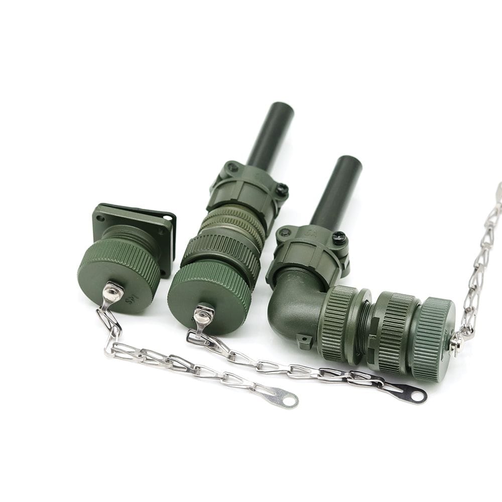
A MIL DTL 5015 cable assembly built to the shell size, insert layout and keying on your drawing: crimp or solder contacts, chain-lanyard dust caps, length and labeling to order.
Last updated: 13 September 2026
Overview
A MIL DTL 5015 cable assembly is the threaded circular power connector that has been dragged through mud, salt sand and forty years of rough handling and mostly kept working. That is why it is still being specified for vehicle, generator and ground-support work when newer families are technically superior on paper: it is big, it is forgiving, it can be mated with gloves on, and a mechanic can service it with a strap wrench. We build to the shell size, insert layout and keying you name, with contacts crimped or soldered per the build and chain-lanyard dust caps fitted where the installation loses caps faster than it replaces them.
How we use the standard. MIL-DTL-5015 is invoked here as the industry-standard interface definition – the shell dimensions, the insert arrangements and the keyway positions that let a plug mate with a receptacle. We manufacture to that interface and inspect to your drawing. We do not hold or claim a qualification to the military specification itself, and nothing here should be read as a certified or listed product. Acceptance is against the drawing and the inspection criteria you specify.
Key Specifications
| Connector family | MIL-DTL-5015 threaded circular, interface per your drawing |
|---|---|
| Styles | Box-mount receptacle, straight plug, right-angle plug |
| Shell size | Per your drawing; insert layout and keyway to match |
| Contact termination | Crimp (removable) or solder, per build |
| Shell finish | Olive drab cadmium plate, or per your spec |
| Dust caps | Chain-lanyard caps fitted where specified |
| Cable | Multi-conductor power bundle sized per contact rating |
| Acceptance | Manufactured and inspected to your drawing |
Reading the part: shell size, insert, keyway
Three things have to agree before two halves will mate, and they are independent of each other.
- Shell size sets the physical diameter of the coupling thread and roughly how many contacts will fit.
- Insert arrangement sets how many contacts there are, what size they are, and where they sit in the face.
- Keyway position – the polarization – stops a plug with the right shell and the right contact count from being rotated into the wrong orientation.
The third one is the one that catches people out. Two connectors with the same shell and the same insert count will physically start to mate in the wrong rotation if the keyways differ, and forcing them damages the contacts. If you are replacing an existing cable, read the shell size, the insert arrangement and the keyway letter off the old part before ordering – a photograph of the mating face usually settles all three.
What kills this cable
| Stress | Failure mode | Design response |
|---|---|---|
| Salt exposure and coastal storage | Corrosion on the shell and at the coupling thread; the nut stops turning | Plate finish selected for the environment, and a mating-that-stays-serviceable approach rather than a cosmetic one |
| Vibration on vehicle and genset mounts | Coupling nut backs off, contacts fret | Safety wire or lockwire provision where specified, and a strain relief that takes the cable load off the shell |
| Cable hanging off the connector | Load transfers into the contacts and the backshell | Backshell and clamp sized to the bundle, support within a short distance |
| Missing dust caps | Contacts contaminated with grit and moisture before the unit is ever mated | Chain-lanyard caps so the cap cannot go missing |
| Repeated field re-termination | Solder joints fatigue, crimp contacts get reused | Removable crimp contacts where serviceability matters, pull force recorded per contact size |
Crimp or solder
Both are legitimate and the right answer depends on what happens after the cable is built.
- Crimp, removable contacts – the serviceable choice. A contact can be extracted and replaced in the field without re-terminating the whole connector, and the joint is consistent if the tooling is right. The tooling has to be right: a hand crimp with the wrong die produces a joint that passes continuity and fails under load.
- Solder – appropriate where the contact is not designed to be removable, or where the build will never be opened. It is less tolerant of vibration unless the strain relief is doing its job, and it is slower to rework.
We record pull force per contact size at setup and re-check in process, which is the control that separates a consistent build from an optimistic one.
Design notes from the build
The backshell is where most of these assemblies actually fail, not the connector face. A bundle that is too large for the clamp will not grip; one that is too small will pull through. We size the clamp to the bundle you specify and add a strain relief that takes the cable load off the contacts, because a connector carrying the weight of its own cable is a connector that will eventually have a loose contact.
Where the installation is coastal or marine, say so at RFQ. The shell finish decision – olive drab cadmium against the alternatives – is an environment decision first and a paperwork question second, and it is much cheaper to get right before the parts are plated.
Typical applications for this MIL DTL 5015 cable assembly
- Military and commercial vehicle power distribution
- Generator sets and ground power units
- Agricultural and construction machinery harnesses
- Rail and rolling stock auxiliary power
- Test rigs and bench supplies where a big threaded connector is wanted, alongside our MIL-DTL-22992 Power Cable Assembly
- Legacy equipment support where the original connector family is no longer stocked
How to specify your build
- Shell size, insert arrangement and keyway – read off the existing part if you are replacing one.
- Style – straight plug, right-angle plug, box-mount receptacle, at each end.
- Contact termination – crimp removable, or solder.
- Shell finish, and whether the installation is coastal.
- Cable – conductor count, size and jacket.
- Dust caps and safety wire provision.
- Length, labeling and quantity.
Workmanship and testing
Assembly and inspection follow IPC-WHMA-A-620 Class 3 workmanship criteria under our ISO 9001 quality management system, and are carried out to the interface dimensions of MIL-DTL-5015 as the industry-standard definition, with acceptance against the drawing and inspection criteria you specify. Every unit passes 100% continuity and pinout testing. Crimp pull force is recorded per contact size at setup and re-checked in process. Conductor range is 32 to 12 AWG.
Custom builds and ordering
Prototypes start from 5 pcs and ship in 3 working days; production orders start at MOQ 500 pcs and ship 14 working days after approval. New overmold or backshell tooling adds about 10 working days, and we hold 100 sets of mold tooling in house. Our Longgang, Shenzhen plant runs four assembly lines with 40 assembly workers and 1,000,000 pcs annual output, and OEM builds ship under your part number. Factory audits and video line tours can be arranged.
Related circular and military-style assemblies
- MIL-DTL-22992 Power Cable Assembly
- MIL-DTL-38999 Series III Military Circular Cable Assembly
- MIL-C-26482 Series I Military Cable Assembly
- MIL-DTL-83513 Micro-D and MIL-DTL-32139 Nano-D Cable
- 38999 High Speed Harness with Overmolded Strain Relief
- Railway Rolling Stock Harness Built to EN 45545-2 Cable Specifications
Full range: custom wire harnesses.
Frequently Asked Questions
Are you qualified to the military specification?
We manufacture to the MIL-DTL-5015 interface dimensions as the industry-standard definition and inspect to your drawing. We do not hold or claim a qualification to the specification itself, and acceptance is against the drawing and criteria you specify.
Can you cross-reference an existing part number?
Usually. Send the part number, or a photograph of the mating face showing the insert layout and keyway. We confirm the three things that have to agree before we quote.
Crimp or solder contacts?
Crimp with removable contacts if the connector will be serviced in the field; solder if it will not. Tell us which and we build to it, with pull force recorded per contact size.
What shell finish should I choose for a coastal site?
Tell us the installation is coastal at RFQ stage. The finish is an environment decision, and it is cheaper to change before plating than after.
What is the minimum order?
Minimum for a prototype run is 5 pcs, out the door in 3 working days. Volume production starts at 500 pcs and ships 14 working days after you approve the sample.
| Connector family | MIL-DTL-5015 threaded circular, interface per your drawing |
|---|---|
| Styles | Box-mount receptacle, straight plug, right-angle plug |
| Contact termination | Crimp (removable) or solder, per build |
| Shell finish | Olive drab cadmium plate, or per your spec |
| Dust caps | Chain-lanyard caps fitted where specified |
| Cable | Multi-conductor power bundle sized per contact rating |
| Shell size | Per your drawing; insert layout and keyway to match |
| Acceptance | Manufactured and inspected to your drawing |