COB LED Power Injection Cable DC 5.5×2.1mm Male to Tinned Bare Wire
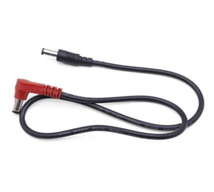
An led power injection cable feeds a COB or SMD strip at a mid-point instead of at one end, so the far end of the run does not dim. 5.5×2.1mm plug to two-core tinned tails, 20 or 18 AWG, 3 m and 5 m.
Last updated: 13 September 2026
Overview
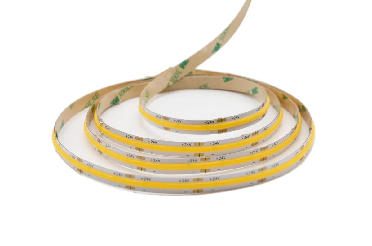
An led power injection cable feeds a strip somewhere in the middle of the run instead of only at one end. Flexible strip is built on a thin copper track with real resistance, so a long run fed from a single point dims toward the far end and, past a certain length, shifts color on a white COB strip. Injecting power at additional points means no single section of track carries the current of the whole run. This lead takes a 5.5×2.1mm supply to two tinned tails that solder straight to the strip pads.
Key Specifications
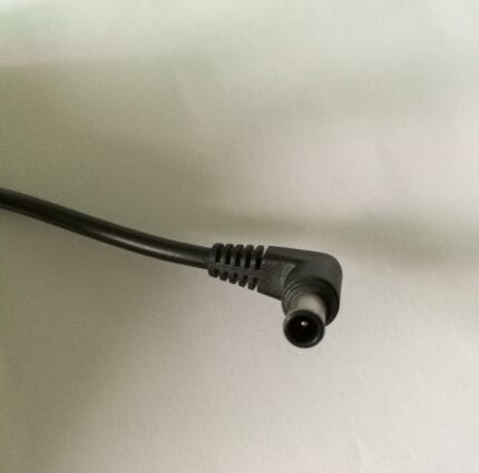
| Connector A | DC barrel plug 5.5×2.1mm, center positive |
|---|---|
| Connector B | Stripped and tinned bare wire, 2 core |
| Conductor options | 0.5 mm2 / 20 AWG, or 0.75 mm2 / 18 AWG |
| Construction | Two-core parallel, red and black |
| Lengths | 3 m / 5 m |
| Voltage | For 12 V and 24 V strip systems |
| Options | Solder-type 5.5×2.1mm socket, JST SM connector version |
| Applications | COB and SMD strip injection, cabinet and display lighting, signage |
| Polarity | Red positive, black negative, marked at the plug |
| Termination | Tails stripped and tinned, ready to solder or clamp |
Why one-end feed dims, and where
The mechanism is straightforward: current flowing along the strip track produces a voltage drop proportional to the length it travels and the current it carries. On a 12 V COB strip the effect starts to be visible on a white setting somewhere past five meters fed from one end, and it gets worse from there. On 24 V strip the same wattage is carried at half the current, so the drop is lower and the usable single-feed run is longer. The fix is never a bigger power supply – the supply is not the problem, the track is.
| Feed arrangement | Track carrying full current | What you see | What to do |
|---|---|---|---|
| Single end feed | The whole run | Far end dimmer; visible past roughly 5 m on 12 V COB | Add an injection point |
| Both ends fed | Half the run, from each end | Even brightness, mild dip at the middle | Enough for most cabinet runs |
| Ends plus mid injection | A quarter of the run | No visible gradient | Use for long architectural runs |
| Injection every 5 m | 5 m at most | Uniform across the whole run | Long corridors, signage, coves |
The distances above are rules of thumb for 12 V strip, not a substitute for a calculation. The numbers that matter are the resistance per meter and the current per meter on your strip datasheet; send them and we will size the injection spacing to them.
Sizing the injection lead
The lead is sized by the current it has to carry and the distance it has to carry it, not by the length of the strip. Undersizing an injection lead reintroduces exactly the drop it was meant to remove, which is why the two builds below exist.
| Build | Suits | Notes |
|---|---|---|
| 0.5 mm2 / 20 AWG | Short parallel leads up to about 3 m | Common choice where the driver sits close to the run |
| 0.75 mm2 / 18 AWG | Longer leads or higher current | Use when the supply is remote or several strips share one feed |
Two-core parallel construction
The lead is a flat two-core cable rather than a round pair. That is deliberate: it sits flat against the mounting surface and follows the strip profile inside an aluminum channel or along a cabinet edge, where a round cable would stand proud and shadow the light. The tails are stripped and tinned, so they solder directly to the strip pads with no further preparation, and the tinned ends do not fray when pushed into a lever connector.
Polarity, fusing and equal lengths
- Observe polarity at every injection point. Reversing one lead back-feeds the section between two points.
- Where a run has more than two injection points, fuse each lead at the supply rather than relying on the driver alone.
- Keep parallel leads from one supply the same length, so each section of strip sees the same voltage.
- Do not join injection leads end to end. Order the single length that reaches.
Where several strips hang off one driver, a distribution point is tidier than a nest of adaptors – see the 8-way fused DC splitter cable for that job.
Termination options
The standard build ends in a 5.5×2.1mm plug for a bench supply or a driver with a barrel output. Where the injector has to be fed from a screw terminal or a distribution block, the plug can be replaced with a solder-type 5.5×2.1mm socket, or the lead can be supplied bare at both ends. A JST SM version is available for controllers and drivers in that connector family, and we build to the connector you name rather than assuming one.
Typical applications for this led power injection cable
- COB strip in aluminum channel under kitchen cabinets and shelving
- Display and retail lighting where a visible gradient is not acceptable
- Signage and light boxes fed from a remote driver
- Long cove and corridor runs off one supply
- SMD strip runs extended with an IP65 waterproof DC 5521 extension
- Exhibition and booth builds that get packed and rebuilt repeatedly
How to specify your build
- Strip voltage and current per meter from the datasheet.
- Run length and how many injection points you plan.
- Conductor – 20 AWG or 18 AWG, or let us size it from the above.
- Supply end – 5.5×2.1mm plug, socket, bare ends or JST SM.
- Lead length, and whether the leads must be matched.
- Jacket color – black or white to suit the channel.
- Quantity, sample or production.
Workmanship and testing
Workmanship follows IPC/WHMA-A-620 Class 3 and the line runs under ISO 9001. Conductors from 32 to 12 AWG are in range. Continuity and pinout are verified on 100% of units before packing; if you specify an ingress rating, seal checking on the batch can be quoted.
Custom builds and ordering
A prototype lot of 5 pcs ships in 3 working days; series orders start at 500 pcs and ship 14 working days after sample approval. We hold 100 sets of mold tooling in house, so a standard body needs no tooling time and a new one adds about 10 working days. OEM and ODM builds go out under your part number and label, with material certificates and first-article reports on request.
Related DC assemblies
- DC 5525 Male to Bare Wire Power Cable
- 14 AWG DC Barrel Pigtail Cable to Bare Wire or Ring Terminals
- 8-Way Fused DC Splitter Cable with Per-Channel Switches
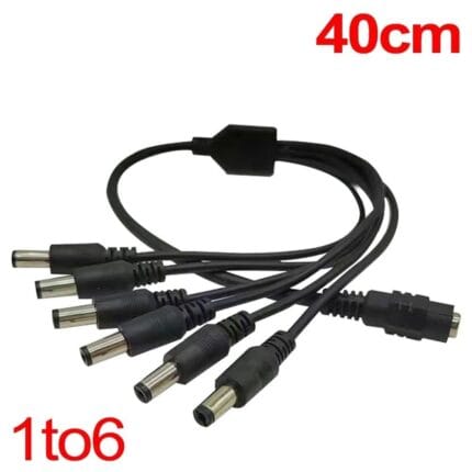
- DC 5521 Power Splitter, 1 Female to 6 Way
- IP65 Waterproof DC 5521 Extension Cable
- Threaded Locking DC Pigtail 5.5×2.1mm, Shielded Right-Angle
Full range: DC plug power cable assemblies.
Frequently Asked Questions
How many injection points do I need?
Work from the resistance and current per meter on your strip datasheet. As a starting rule, inject every 5 m on 12 V strip and check the far end with the run at full brightness before you close it up.
Can I just fit a bigger power supply?
No. The drop is in the strip track, not in the supply. A bigger supply raises the current and can make the gradient worse.
18 AWG or 20 AWG?
20 AWG suits short parallel leads up to about 3 m. Use 18 AWG for longer leads, higher current, or where several strips share one feed.
Do the tails need preparing before soldering?
No. They arrive stripped and tinned, ready to solder to the pads or push into a lever connector.
Can I have a socket instead of a plug?
Yes. A solder-type 5.5×2.1mm socket, bare ends at both sides, or a JST SM version are all standard options.
| Connector A | DC barrel plug 5.5×2.1mm, center positive |
|---|---|
| Connector B | Stripped and tinned bare wire, 2 core |
| Conductor options | 0.5 mm2 / 20 AWG, or 0.75 mm2 / 18 AWG |
| Construction | Two-core parallel, red and black |
| Lengths | 3 m / 5 m |
| Voltage | For 12 V and 24 V strip systems |
| Options | Solder-type 5.5×2.1mm socket, JST SM connector version |
| Applications | COB and SMD strip injection, cabinet and display lighting, signage |
| Polarity | Red positive, black negative, marked at the plug |
| Termination | Tails stripped and tinned, ready to solder or clamp |