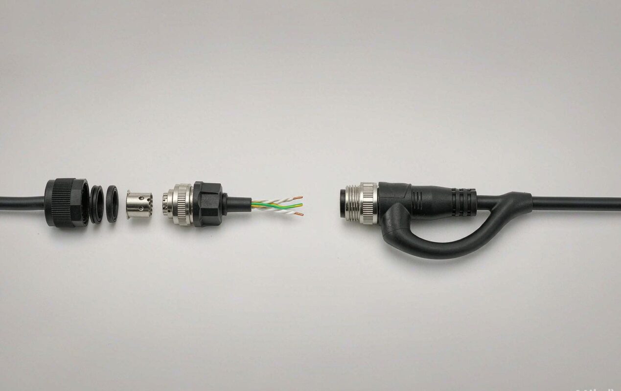
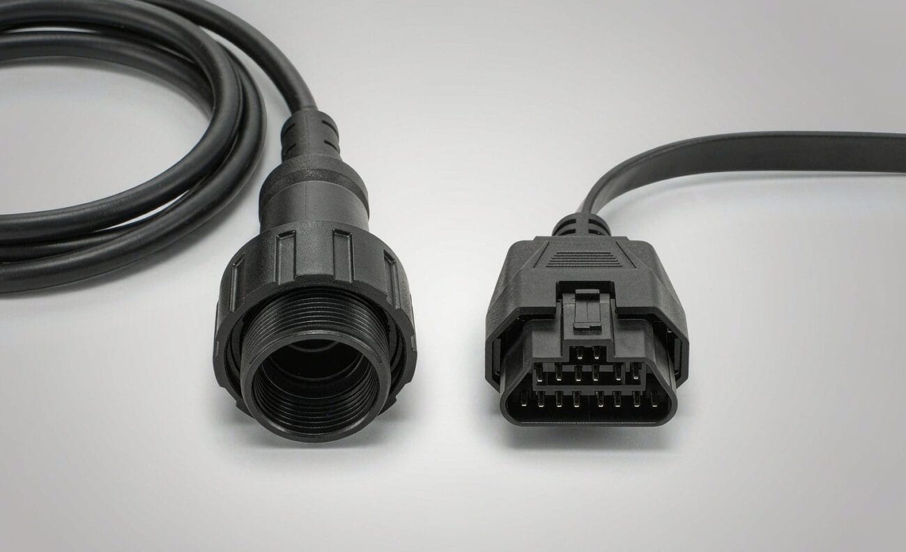
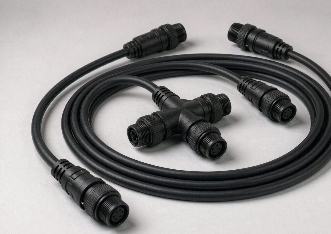
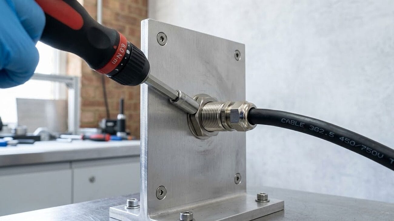
An overmolded cable design looks like a cosmetic detail and behaves like a structural one. It decides how load enters the connector, whether the assembly survives a washdown, how the cable sits in a panel, and how the part feels in a technician’s hand. Those functions should be settled on paper, because the alternative is discovering them after the steel is cut — which is the expensive place to discover anything.
Here is what we ask an engineer to define before tooling starts, and why each item changes the mold.
The overmolded cable design is a functional part
Its job can include strain relief, sealing, grip, orientation, identification and protection. Prioritize these functions before choosing appearance.
Rank them, because they compete. A soft, grippy overmold is comfortable to handle but wears faster in a drag chain. A hard, thin-walled boot survives abrasion but transmits more bending load to the solder joints. Once the priority order is on the drawing, the material and wall thickness arguments mostly resolve themselves.
Strain relief. How much pull and bend load reaches the termination.
Sealing. IP rating at the connector face and at the cable exit.
Grip and orientation. Finger features, keying, and any “this end up” geometry.
Identification. Molded part number, logo, or polarity arrow.
Protection. Impact, abrasion, or chemical exposure at the cable entry.
Define the insert and cable exit
Connector retention, available bonding surface, cable diameter, exit angle and minimum bend zone all affect the mold concept.
The insert is what the plastic has to grip. A connector with a flat, moldable body gives the material something to lock onto; a smooth cylindrical shell with no shoulder does not, and the mold then has to add mechanical retention features to stop the boot spinning or pulling off. Cable diameter matters more than most drawings admit — the mold is bored to a specific jacket size, and a change from 5.0 mm to 5.5 mm after tooling is not a free change.
Connector part number and the mating half.
Bonding surface: flat areas, shoulders, undercuts available to the material.
Cable outer diameter, and whether it is toleranced or nominal.
Exit angle: straight, 45°, or 90°.
Minimum bend zone — how close to the boot the cable may be bent in service.
Match material to the environment
Flexibility, bond behavior, temperature, oil or chemical exposure and ingress requirements should be discussed as a group.
Two properties get quoted most often and matter least in isolation: durometer and color. What actually decides field performance is how the material bonds to the specific cable jacket in front of it, and how it behaves at the temperature extremes of the application. A PVC overmold on a PUR jacket can look perfect on the sample and delaminate after a winter in a cold store.
PVC. Lowest cost, good all-round, stiffens in the cold.
TPE. Softer grip, wider temperature window, good for handheld and medical.
TPU / PUR. Abrasion and oil resistant; the default for drag chain and outdoor.
Low-smoke zero-halogen. Where flame and smoke behavior is specified.
We will propose the material and flag any bonding risk against the jacket you have chosen — that conversation is cheaper before tooling than after it.
Plan the prototype checkpoint
Use the first molded samples to confirm mating clearance, pull behavior, cable exit and installation — not only color and finish.
Approve the sample the way it will be used: mate it to the real connector, route it through the real panel, pull it by hand, and leave one in the environmental chamber if the application has one. Approval on appearance alone is the most common reason a second tool revision is needed.
Overmold and jacket material: pick your environment
Choose the condition the assembly has to survive. The recommendation below is the material we would start a quote from, and what we still need you to confirm.
Material choice is a starting point, not a substitute for testing. We run a compound recommendation past the actual media, temperature and flex cycle before a tool is cut. For a full side-by-side, see PVC vs PUR vs TPE cable jackets.
Tooling: what drives cost and lead time
An overmold tool is a one-off cost, not a per-piece one, and it is almost always smaller than buyers expect. What drives it is not size but complexity: the number of cavities, whether the insert has to be loaded by hand, side actions for undercuts, and how tight the cosmetic requirement is.
Our mold shop is in the same building as the assembly lines, so a new tool adds about 10 working days rather than the six to eight weeks a tool sourced separately usually takes. We hold 100+ overmold tool sets on site, the tooling is cut and maintained by our own people, and the mold belongs to you — we do not reuse it for another customer’s program. See the mold making and tooling capability.
Minimum order quantity is 500 pcs per part number for production runs, while prototypes and samples are built from 1 to 50 pcs. That volume exists for a practical reason: below it, the setup and verification time per build costs more than the parts do, and the unit price stops making sense for either of us.
Overmolded cable design FAQ
Can you overmold a connector we supply?
Yes — free-issue connectors are normal. Send the parts with the drawing and we will confirm the bonding surface and the retention features before quoting. If a specified connector has a long lead time, we will flag equivalents rather than let it hold the schedule.
Can an existing tool be modified instead of cut new?
Often yes, if the change is a cable diameter, a length or a logo. A change to the insert geometry usually means a new cavity. We will tell you which one you are looking at before you commit.
How long does a new overmold tool take?
About 10 working days from approved design, because the tool is cut in-house. Prototypes follow in 3 working days and production in 14 working days after sample approval.
Who owns the tooling?
You do. It is maintained by us while it is in use and it is never run for another customer’s part.
Next step: send the connector, the cable specification and the environment, and we will come back with a mold concept, a material recommendation and a tool lead time. Start with a build-to-print inquiry, or request a production review.
MIL-DTL-38999 vs M12 compared across seven dimensions: only four are separated by a class. Current ratings, temperature, mating cycles, mass and the base trap in price comparisons.
Shielded vs unshielded cable: a 50 mm pigtail adds 43 nH and 27 ohms at 100 MHz, while a Grade 1 cable shield is under 60 milliohms per metre. NASA measured 30 dB.
M12 distribution box selection: total ratings range from 8 A to 12 A across six vendors, and a 10 m trunk on 0.75 mm2 drops 4.16 V at 8 A, below the 20.4 V floor.