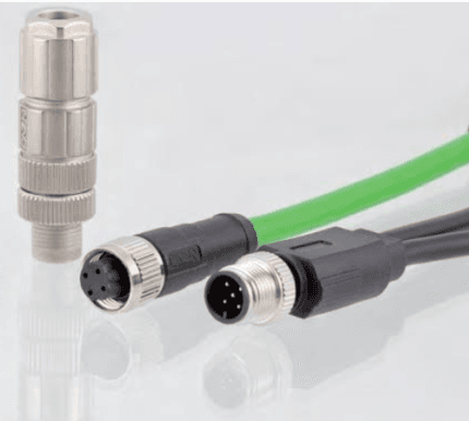
M5 3-Pin Sensor Cordset for Micro Sensors
An M5 3-pin sensor cordset is the one connector in the metric family that can disappear entirely behind a sensor head: a 5 mm thread, three gold-plated contacts rated 1 A at 60 V, and an overmold small enough to clear a 10 mm mounting hole. Straight or right-angle, PVC or PUR, any length.
Overview
An M5 3-pin sensor cordset is the one connector in the metric family that can disappear entirely behind a sensor head: a 5 mm thread, three gold-plated contacts rated 1 A at 60 V, and an overmold small enough to clear a 10 mm mounting hole. Straight or right-angle, PVC or PUR, any length.
Where an M5 3-Pin Sensor Cordset Beats Every Larger Option
Face space is the real currency on a modern machine. A pick-and-place head carrying six sensors does not have six M8 positions to give away; a dental pump, a lab-on-a-bench module or a compact cobot gripper has even less. The M5 interface, standardized in the IEC 61076-2-105 detail specification, was written for exactly this: the smallest threaded circular connector still robust enough for a production floor, with an A-coded keyway so a 3-pin plug can only go on a 3-pin socket.
The Numbers Behind the Small Shell
Standard M5 builds carry 1 A per contact at 60 V AC/DC on 26 AWG (0.14 mm2) conductors – brown, blue and black in the 3-pin layout, which maps one-to-one onto the wiring of every common two-wire and three-wire micro sensor. Contact resistance sits at 5 milliohm or better on gold-over-nickel brass contacts, and the coupling nut is nickel-plated brass, with stainless steel available for washdown lines. Mating life is rated at 500 cycles and above.
Applications We Build For Most
Three families dominate the order book. First, micro inductive, capacitive and photoelectric sensors packed onto semiconductor handlers, packaging machinery and assembly stations. Second, end-of-arm tooling: gripper fingers, vacuum check sensors and part-present switches on small collaborative robots, where every gram on the wrist is payload lost. Third, portable and mobile devices – electric-bike speed sensors, miniature navigation modules on unmanned vehicles, and hand-carried test instruments where the harness hangs off the device all day.
Getting the Fitment Right the First Time
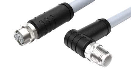
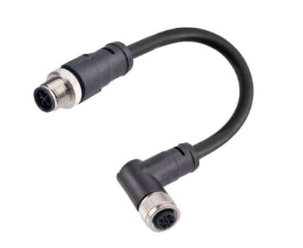
Tell us the sensor manufacturer and part number, or send a phone photograph of the connector face next to a coin, and we will confirm gender, keyway and pinout before anything is molded. The right-angle variant deserves special mention: most M5 field failures we see are not electrical at all, they are straight plugs forced against a bracket until the jacket kinks. If the cable has to leave the sensor along the panel, order the elbow.
Jacket Choices for the Working Environment
PVC is the cost-effective indoor default. PUR belongs wherever cutting fluid, oil or deck abrasion appears – packaging lines, machine tools, mobile equipment. TPU is the pick for constant flexing and for anything an operator handles, because it stays supple and quiet in the hand. The overmold compound is matched to the jacket so strain relief and cable age at the same rate instead of fighting each other.
Ordering and Custom Options
Specify pin count, length, jacket compound and outlet direction, and we return a drawing with the exact ratings for your build before production. Cable lengths run from short pigtails under 0.5 m to long drops, with no minimum order quantity that forces you to overbuy. Hybrid and splitter builds – one connector feeding two sensors – are molded as a single piece rather than spliced.
How Each Cordset Is Verified
Every unit gets a 100 percent continuity check and a hipot test, and mating pairs are go/no-go gauged so batch-to-batch seating stays effortless. Pull-out force is checked after overmolding, and sealed builds are leak tested. Material declarations and test reports ship in the carton; name any market approval at the enquiry stage and we quote to it.
What to Put on the Drawing for a M5 3-Pin Sensor Cordset
A m5 3-pin sensor cordset is released against a drawing, not a catalog description. Put the connector family and keying on each end, the pinout or polarity map, the finished length measured between the mating reference planes, the cable construction you want, and the acceptance tests you expect. If the M5 3-pin sensor cordset has to clear a panel cutout or a bracket, give that envelope too. Anything left open is agreed in writing before tooling or a production slot is committed.
Where a value is not fixed by your drawing we do not invent one. Contact rating, jacket material, sealing class and test limits are recorded as confirm per build, and the released drawing is what the first article is checked against. Send a marked-up sample if a drawing is not available; we confirm the pinout back to you in writing before any M5 3-Pin Sensor Cordset is built.
How to Request a Quote for a M5 3-Pin Sensor Cordset
Send a drawing or BOM, a physical sample, or a written requirement. We log the interface, the application conditions, the environment and the target quantity together, then return an acknowledgement with a list of anything still missing. Pricing is confirm per RFQ and is quoted against the released specification, not against a generic m5 3-pin sensor cordset description.
If the design is not final, say so: we quote the prototype route and hold the production tooling decision until the first article is approved. Drawings are handled under a mutual NDA before they are received. The same document then carries the build from sample through repeat orders, which keeps the M5 3-pin sensor cordset consistent across batches.
Fit Check Before You Release the Build
Before release, mate a sample to the real counterpart, not a similar one. Check the keying, the wrench or finger clearance around the coupling, the exit direction relative to the nearest bracket, and the length between the mating reference planes. On compact sensors and tight machine envelopes, a M5 3-pin sensor cordset that fits the panel but fouls the cover is a common and avoidable revision.
Record the cable diameter you qualified against, especially where a gland or seal is involved. A M5 3-Pin Sensor Cordset built at either edge of a seal window does not forgive tolerance scatter the way one in the middle does. Photographs of the fitted sample are kept with the part reference so a later order can be compared against the same configuration.
Electrical Verification Before Shipment
Every m5 3-pin sensor cordset is checked for continuity and pinout against the released drawing before packing, and the mating faces are inspected for full engagement. A swapped core is cheaper to find at the bench than in the field. Where the drawing calls for insulation resistance, dielectric withstand or retention testing, those limits come from your specification and are reported against it; we do not substitute our own numbers.
First article inspection is issued to your format when the order calls for it, with dimensional results and photographs of the critical features. Sealed sections are screened on the agreed test setup. Test scope is fixed in writing before production release so the report that arrives with the shipment describes the build you actually approved.
Packaging, Labeling and Revision Control
Assemblies are individually bagged with contact protection, and OEM labeling, part numbers and bulk packs are available. Put the label text, the bag mark and any barcode requirement on the order so the packing matches your receiving process. For compact sensors and tight machine envelopes, a labeled bag also stops a nearly identical lead from being fitted to the wrong unit during a service visit.
Every revision carries a reference tied to your part number. Obsolete revisions are retained so a repeat order matches the build you approved, and a change to length, pinout, jacket or connector is only made after written confirmation. That record matters more on a m5 3-pin sensor cordset than a part number alone, because two builds can look the same and wire differently.
Related Cable Ranges
This cordset is the small end of the Circular M-Series Cable Assemblies. For threaded waterproof builds in larger sizes see Screw-Lock Molded Cable, and for panel feedthroughs see Panel Mount Cable. The interface is defined by the IEC 61076-2-105 detail specification.
RoHS and REACH declarations are provided per project together with the agreed test reports; the documentation scope is listed under certifications and compliance. If your drawing specifies a UL style, we build to that drawing and supply the UL reference with the shipment instead of substituting an equivalent. Flex life is a construction decision made before tooling, following the conductor and jacket approach set out under continuous-flex construction and flex-life testing. The wider context is covered under what automation programs ask for. Any tooling we cut for this part stays yours, maintained in our own tool room under your part reference.
| Connector series | M5 (IEC 61076-2-105), M8 / M12 in same family |
|---|---|
| Coupling thread | M5 x 0.5 |
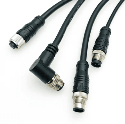
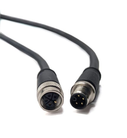
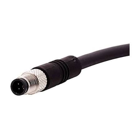
| Pin count | 3 (image shows male straight), 2, 4 |
| Coding | A-coded |
| Rated voltage | 60 V AC/DC |
| Wire gauge | 26 AWG (0.14 mm2), Other on request |
| Jacket material | PVC, PUR, TPU |
| Orientation | Straight, Right-angle |
| Ingress rating | IP67 when mated |
| Rated current | 1 A per contact |