Magnetic Pogo Pin Cable USB-C for Medical and Wearable Devices, 2 / 4 / 8 Pin
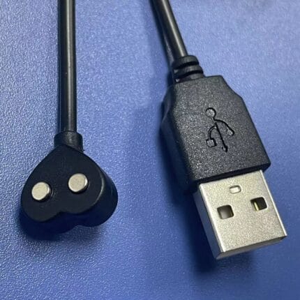
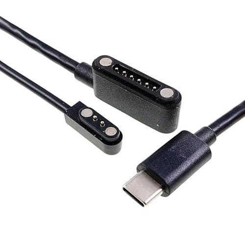
A magnetic pogo pin cable lets a medical or wearable device charge and sync without an open socket that can snag a lead or trap fluid. It is built in 2, 4 and 8 pin versions with a USB-C source end, gold plated spring contacts and a breakaway release, to the pinout and pull force you specify.
Overview
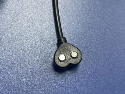
A magnetic pogo pin cable replaces the open socket on a medical or wearable device with a flat, sealed pad of spring-loaded contacts. Nothing has to be pushed into a hole that can trap fluid, snag on clothing, or lever against a PCB when somebody walks past the lead. The cable head carries the pins in a keyed housing, the device carries the pads, and the two release under a straight pull. We build it in 2, 4 and 8 pin versions with a USB-C source end, to the pinout and pull force you specify.
Key Specifications
| Input connector | USB-C plug |
|---|---|
| Device interface | Magnetic pogo pin, keyed housing, 2 / 4 / 8 pin |
| Contact plating | Gold plated spring-loaded pins |
| Breakaway force | At least 1.5 kg class – confirm per your drawing |
| Mating life | At least 10,000 cycles class – confirm per your drawing |
| Jacket options | Medical-grade silicone or TPU, specified for wipe-down cleaning |
| Protection | Reverse polarity protection |
| Ingress rating | IPX7 rated build class where specified |
| Temperature range | -20 to +85 C class – confirm per your drawing |
| Build process | Documented revision-controlled build with lot traceability; clean-assembly option |
| Applications | Portable medical devices, patient wearables, industrial handhelds, exoskeletons, robots |
Why a magnetic pogo pin cable beats a friction-fit plug on a worn device
The convenience story is the small half of the argument. The engineering story is what happens when the lead is pulled: a friction-fit plug hands the whole yank to the socket, and the socket hands it to the solder joints holding it to the board. On a body-worn monitor that is how a port gets torn off. A magnetic interface releases at the joint designed to let go, so the failure is a reconnect instead of a repair. The second reason is the hole itself: an open socket on a device that is wiped down or worn against skin has to be sealed or drained, and both cost money and space. A pad does not.
How the contact actually closes
A pogo pin is a plunger in a barrel, held out by a spring, with a defined travel and a defined force at the working height. The contact is a small point under constant spring load, and it moves every time the cable is nudged. That is why plating matters more here than on a plug you insert once: a surface film on a moving point raises contact resistance over the life of the product, and the symptom is a slow increase in voltage drop rather than an open circuit. The specification that matters on your drawing is the plating over the nickel underplate, not the word “gold”.
The magnet supplies the holding force, not the electrical path – the pins carry the current. That is why a magnetic connector can still fail: a head sitting crooked can hold magnetically while one pin rides high.
How contact resistance turns into heat
Do the arithmetic on your own numbers before you freeze the pin count. Heat at the interface is I squared R, and the R that matters is the pin contact resistance plus the joint behind it. Double the current and that heat goes up four times, so a fast-charge profile is a reason to revisit pin count, plating and conductor size. On a device worn against skin a warm pad is a comfort complaint and a safety review at once, which is why we ask for charge current and duty cycle before quoting.
Choosing 2, 4 or 8 pins
| Pin count | What it carries | Typical use | What to watch |
|---|---|---|---|
| 2 pin | Charge only, plus and minus | Simple wearables, handhelds charged from a cradle | No sense line means the device cannot tell what it is plugged into |
| 4 pin | Charge plus one signal or sense pair | Docking, battery sensing, a button or an LED in the head | Decide which two pins are sense before layout, not after tooling |
| 8 pin | Charge plus several signal lines | Instrumented devices, docked monitors, service and data ports | More pins means tighter pad tolerances and more ways to seat wrong |
Why magnets let go, or seat wrong
- Wrong release axis. A magnetic joint releases on a straight pull; a sideways knock levers it off far more easily.
- Debris on the pad. Skin oils, residue and dust hold the head off the pads by a few tenths of a millimeter – enough to open a signal pin.
- Steel nearby. A mounting plate or ferromagnetic shield behind the device steals flux and cuts holding force.
- No keying. Without a locating feature the head can sit 180 degrees out and still hold.
Cleaning, disinfection and skin contact
Anything used in a clinical area gets wiped, and the wipe-down agent is a materials question before it is an electrical one. Silicone and TPU are the two jacket compounds we specify for this duty because they survive repeated wiping without cracking or going tacky; tell us which agents the unit sees and we confirm the compound on your drawing. The flat pad helps too: there is no cavity for fluid to pool in and no contact to corrode between uses. IPX7 class construction and a clean-assembly option are available where the build calls for them.
Plating and service life
Mating life quoted by comparable products lands at 10,000 cycles class and release force at 1.5 kg class. We record both as leads from public listings rather than as verified ratings, and replace them with measured values once the pin and magnet selection is frozen. The two pull against each other: a connector that lets go easily also lets go when you did not want it to.
Typical applications for this magnetic pogo pin cable
- Patient wearables and portable monitors, where the pad replaces a socket that would have to be sealed – the same interface family as our smart watch magnetic charging cable
- Clinical carts and handheld terminals that get wiped down between patients
- Industrial handhelds and scanners, alongside sealed options such as the IP67 DC to USB-C cable
- Exoskeletons and docked-charging AGVs, where a reverse polarity protected DC lead is the other half of the setup
What to send us to get a quote
- The pinout, and which pins carry current rather than signal.
- Charge current and duty cycle, so pin count and conductor size can be checked against interface heating.
- Target release force, and how the device is worn or mounted.
- The wipe-down agents, and any skin-contact rule that drives jacket material.
- Your pad layout and keying, or the housing drawing if we build both halves.
Five pieces is the prototype minimum for Magnetic Pogo Pin Cable builds, shipping in 3 working days. The production minimum is 500 pcs, delivered 14 working days after sample sign-off. Tooling not already held adds around 10 working days. Magnetic orders ship as OEM or ODM under your part number and labeling we provide material certificates and first-article reports when asked.
Workmanship and testing
IPC/WHMA-A-620 Class 3 is the workmanship bar for Magnetic Pogo Pin Cable builds, and ISO 9001 is the system behind the line, from 32 to 12 AWG. Each Magnetic unit passes a continuity and pinout check before it ships, and seal checking is quoted whenever an ingress rating is on the drawing.
Every production run can ship with RoHS and REACH declarations and the electrical report agreed at quotation; see certifications and material declarations. UL styles and other named approvals are built to drawing: we source to the style you specify and document it, rather than asserting a listing we do not hold. Production runs on the same lines described under cable assembly and wire harness production, where cutting, termination, molding and 100 percent electrical verification sit under one roof. The wider context is covered under what medical builds require beyond the cable. Tooling is quoted separately, cut in-house rather than brokered out, and owned by you.
Frequently Asked Questions
Does the magnet carry the charging current?
No. The magnet only holds the head on the pads; the spring-loaded pins carry current and signal. That is why pin count, plating and spring force decide performance.
Can you match a pad layout we already have on a device?
Usually yes. Send the pad layout or the magnet housing drawing and we build the cable head to it. We can supply both halves.
Will the cable release during normal use?
It releases on a straight pull above the target force, which is the point. Release during normal movement usually means a side load, a ferromagnetic part behind the device, or a target force copied from a listing.
Can it be used for data as well as charging?
Yes on the 4 and 8 pin versions. Tell us which pins carry data or a sense line at the quoting stage, because pad spacing and routing follow from that.
Related assemblies
| Input connector | USB-C plug |
|---|---|
| Device interface | Magnetic pogo pin, keyed housing, 2 / 4 / 8 pin |
| Contact plating | Gold plated spring-loaded pins |
| Breakaway force | At least 1.5 kg class – confirm per your drawing |
| Mating life | At least 10,000 cycles class – confirm per your drawing |
| Jacket options | Medical-grade silicone or TPU, specified for wipe-down cleaning |
| Protection | Reverse polarity protection |
| Temperature range | -20 to +85 C class – confirm per your drawing |
| Build process | Documented revision-controlled build with lot traceability; clean-assembly option |
| Applications | Portable medical devices, patient wearables, industrial handhelds, exoskeletons, robots |
| Ingress rating | IPX7 rated build class where specified |