38999 High Speed Harness with Overmolded Strain Relief for 10GbE Links
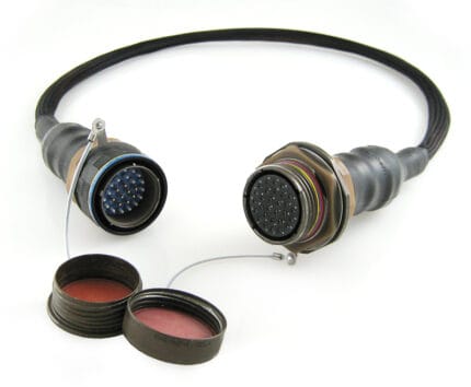
A 38999 high speed harness carrying 10GBASE-T, USB and video through shielded size 8, 12 and 16 contacts, with a 360 degree backshell interface and an overmolded transition at the point where these assemblies normally fail. Built to your print.
Last updated: 13 September 2026
Overview
Rugged vehicle and shelter electronics increasingly push Ethernet, USB and video through one circular connector instead of through a nest of separate ruggedized interfaces. A 38999 high speed harness built that way is not simply a rugged shell with Ethernet contacts dropped into it. The contact selection, the pair handling, the shield termination and the strain relief all have to be designed together, because the place these assemblies fail in service is almost always the backshell rather than the contact. We build to your print and we agree those four things before any tooling is cut.
Key Specifications
| Build Type | Build to print or build to sample |
|---|---|
| Shell Style | MIL-DTL-38999 Series III style |
| Contact Sizes | Size 8, 12 and 16 shielded contacts |
| Contact Types | Coax, twinax, quadrax, octaxial and power mixed |
| Protocols | 10/100/1000BASE-T, 10GBASE-T, USB 3.0, HDMI, DisplayPort, SATA |
| Shielding | 360 degree shield termination at the backshell interface |
| Strain Relief | Overmolded transition, length per drawing |
| Testing | Continuity, dielectric withstand, shield continuity |
Two decisions are made before any wire is cut, and both are mechanical:
| Decision | What it sets | Where it goes wrong |
|---|---|---|
| Shell size | How many contacts, and which sizes, fit in the shell | A layout that fits on paper but leaves no room for the pair bundles at the backshell |
| Keyway position | Which receptacles the plug will and will not mate with | Two connectors on one panel that cross-mate after a service swap |
| Contact size | Size 8, 12 or 16, deciding what each position can carry | A size 16 used where the protocol needs the geometry of a size 8 |
| Contact type | Coax, twinax, quadrax, octaxial or power | A power contact sitting in a position the harness treats as a differential pair |
| Plating and shell finish | Corrosion and conductivity behavior in your environment | Specified by habit rather than by where the vehicle actually operates |
If you are replacing an existing assembly, the shell size and keyway are usually stamped on the connector body. Reading them off the old part before specifying saves a round trip.
Treat the pair as the component and the connector as its housing. On a twisted pair the twist is what rejects the noise, and every millimeter of untwist at the contact is a millimeter of antenna:
| Protocol | Contact type we would expect | What the build has to protect |
|---|---|---|
| 10/100/1000BASE-T | Quadrax, or four signal contacts in a defined pair layout | Pair twist held to the contact, and equal drain lengths |
| 10GBASE-T | Shielded size 8 contacts built for the data rate | Pair geometry and a consistent lay length from one build to the next |
| USB 3.0 and video | Shielded high speed contacts with defined impedance | Bend radius at the backshell, which is where links quietly fall over |
| SATA and storage links | Shielded differential contacts | Separation from adjacent power contacts in the same shell |
| Power in the same shell | Size 12 or 16 power contacts | Physical separation from the high speed positions, agreed on the drawing |
The last row matters more than it looks. Putting power and high speed data in one shell is normal; putting them in adjacent positions without an agreed layout is not.
Shield termination: 360 degrees or nothing
A pigtail drain is the cheapest way to end a screen and the most common reason a rugged link behaves differently on the bench than in the vehicle. We terminate at a continuous 360 degree interface at the backshell, so the screen continues through the connector instead of stopping at a junction. Where the design calls for a controlled exception, such as a screen floated at one end, we build it as specified and record it, rather than deciding on the line.
The overmolded transition
The backshell area is where these assemblies fail. We overmold the transition so the cable screen lands on a full circumferential interface and the bending load transfers into the molding instead of into the crimp. Shell size, cable outer diameter and molding length are agreed on the drawing before tooling. We hold 100 sets of mold tooling in house, so a standard body costs no tooling time and a new one adds about 10 working days.
Typical applications for this 38999 high speed harness
- Vehicle and shelter electronics carrying Ethernet and video through one shell
- Ground support and test sets for avionics bays
- Radar, electro-optic and mission system racks
- Machine vision in a washdown or outdoor enclosure
- Mixed power, signal and high speed builds in a single connector
Verification
Continuity, dielectric withstand and shield continuity are checked on every unit. Data rate performance belongs to the complete channel rather than to the harness alone, so where a protocol has to be demonstrated we agree the test method and the fixtures with you in advance and report measured results instead of repeating a catalog claim.
Workmanship and ordering
Assembly and inspection follow IPC/WHMA-A-620 Class 3 workmanship criteria under our ISO 9001 quality management system, and every unit passes 100% continuity and pinout testing before it is packed. Conductor range is 32 to 12 AWG. Where an ingress rating is specified we can quote seal checking on the production batch.
Prototype builds start from 5 pcs and ship in 3 working days; production orders start at MOQ 500 pcs and ship 14 working days after approval. New overmold tooling adds about 10 working days. OEM and ODM builds ship under your part number and labeling, with material certificates and first-article reports available on request.
Frequently Asked Questions
Can you carry power and 10GbE in the same shell?
Yes, with the right contact arrangement. Send the arrangement and the protocol per contact and we will confirm what fits and where the separation should sit.
Do you overmold the backshell?
Yes. That is the standard way we build these, because the backshell is where they fail in service.
Can you cross an existing part number?
Send it and we will cross what we can. Shell size, keyway and contact arrangement are usually enough to identify the build.
What is the prototype quantity?
Prototypes start from 5 pcs and ship in 3 working days. Production runs start at 500 pcs and ship 14 working days after approval.
Related assemblies
- MIL-DTL-38999 Series III Military Circular Cable Assembly
- Rugged RJ45 IP68 Military Ethernet Cable
- Micro-D Shielded Jumper with Twisted Pair and Coax Mix for Avionics
- Lightweight UAV Wire Harness for eVTOL Propulsion and Avionics Bays
- Cat6A M12 X-Code Link Cable, X-Coded 8-Pin Both Ends, IP67
- USB3 Vision Camera Cable with Locking Screws for Machine Vision
Full range: Custom Wire Harnesses.
| Build Type | Build to print or build to sample |
|---|---|
| Shell Style | MIL-DTL-38999 Series III style |
| Contact Sizes | Size 8, 12 and 16 shielded contacts |
| Contact Types | Coax, twinax, quadrax, octaxial and power mixed |
| Protocols | 10/100/1000BASE-T, 10GBASE-T, USB 3.0, HDMI, DisplayPort, SATA |
| Shielding | 360 degree shield termination at the backshell interface |
| Strain Relief | Overmolded transition, length per drawing |
| Testing | Continuity, dielectric withstand, shield continuity |