J1939 9-Pin Y Splitter Cable for ELD and GPS Trackers
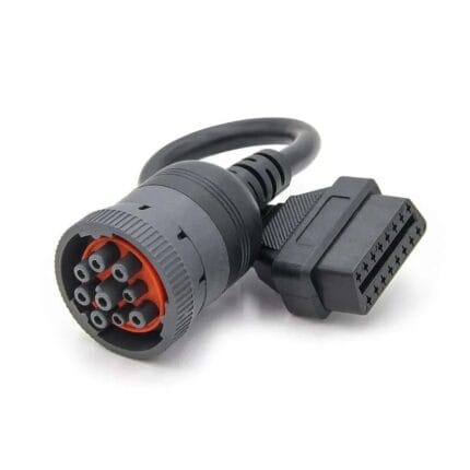
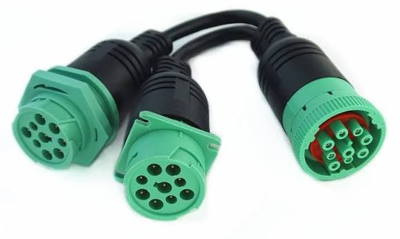
This J1939 9-pin y splitter lets an ELD or GPS tracker stay on the diagnostic port while leaving a second live socket for service tools. Passive straight-through wiring, molded bodies, 0.3 m stub, built to the pinout you send.
Last updated: 13 September 2026
Overview
A J1939 9-pin y splitter turns one vehicle diagnostic port into two, so a
telematics device can stay permanently connected while a service technician still gets a live
port. That is the whole job, and it sounds trivially simple until you look at what happens when
people solve it the wrong way. The fleet device has to stay on the port every hour the truck is
working; the technician needs the same port for maybe twenty minutes a month. A passive
pass-through splitter satisfies both without cutting anything.
Key Specifications
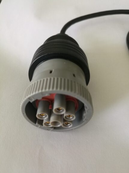
| Connector A | 9-pin round diagnostic plug, compatible with Deutsch HD10 / HD16 series |
|---|---|
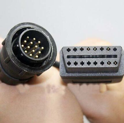
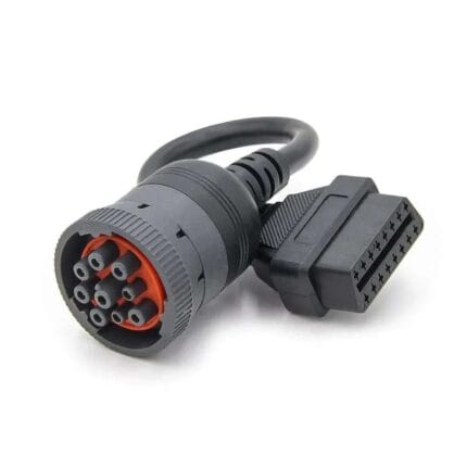
| Connector B | 2 x 9-pin round receptacles (or 1 x 9-pin + 1 x J1962 16-pin, to order) |
| Wiring | Straight through on all populated pins: CAN-H, CAN-L, J1708 pair, battery, ground |
| Conductor | Tinned copper, 20 to 18 AWG |
| Outlet style | Straight or right-angle bodies |
| Stub length | 0.3 m between bodies |
| Function | Passive pass-through, no buffering or protocol conversion |
| Termination | No terminating resistor fitted as standard; 120 ohm build on request |
| Port loading | Passive wiring only; total connected device count and stub length kept low |
Why you cannot just splice a second connector in parallel
The tempting fix is a tee made with two receptacles and some solder. On a power wire that
works. On a vehicle network it introduces a stub: a length of conductor hanging off the bus that
is not part of the designed trunk. Every stub adds capacitance and creates a reflection point,
and the faster the network, the shorter the stub has to be before it starts eating the signal
margin. Two devices, two stubs, and a longer untwisted section where the joint was made is
exactly the combination that produces faults which appear under load, disappear in the yard, and
never reproduce on the bench.
| Approach | What it does to the bus | What it does to the vehicle | Verdict |
|---|---|---|---|
| Unplug the tracker for service | Clean connection every time | Loses the trip record and the ELD data for that period | Compliance problem |
| Cut into the vehicle harness | Adds a permanent joint and a stub | Modifies the factory harness, usually voiding something | Last resort |
| Spliced tee made on the bench | Two unmatched stubs, unknown length | No mechanical support at the port | Intermittent faults |
| Molded passive Y splitter | One molded body, short controlled stub | Nothing permanent, reversible in seconds | The right answer |
The mechanical half of the argument matters just as much. A hand-made tee hangs off the
port and works the connector loose. A molded splitter with a short stub and strain relief at
every body carries its own weight.
Bus loading, and where termination comes in
A CAN bus is
designed as a trunk with a terminating resistor at each end, and every node taps onto it. Adding
nodes adds load, and adding stub length adds reflections; both shrink the margin before errors
start. In practice a second device on a molded splitter is well inside what a
healthy truck network tolerates, but there are two things worth knowing before you order:
how many devices you intend to leave plugged in permanently, and whether the network already has
its terminating resistors in place. Adding a third 120 ohm termination where two already exist
will pull the bus out of specification, which is why our standard build ships without one and we
fit a terminating resistor only when you ask for it.
Power pins: the part people forget
The port is not only data. Pins A and B carry battery negative and unswitched battery
positive, and that is what keeps a tracker alive. The consequence is shared current: everything
you leave plugged in draws from the same supply path, so add up the draw of the tracker, the
ELD and whatever else is on the port before you assume it will all run. On a vehicle that parks
for a week, the more important question is what happens to the battery, and a device with its
own low-voltage cutoff is worth specifying.
Which signal pairs the splitter has to carry
A 9-pin port can carry more than one network, so the splitter is wired straight through on
every populated pin rather than picking the ones we think you need.
- CAN high and CAN low — the J1939 pair, on C and D in the common
assignment. - J1708 / J1587 pair — the legacy link still present on a lot of in-service
equipment, on F and G in the common assignment. - Battery and ground — for powering the connected device.
- Shield — carried through so the screen stays continuous.
Because the assignment varies by maker, the harness is built to the pinout you send rather
than to one assumed standard. If you are not sure, send a photo of the port and the device part
numbers and we will confirm before production.
Mechanical detail
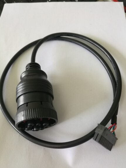
- Molded 9-pin plug on the vehicle side, two molded 9-pin receptacles on the outlet side.
- Straight or right-angle outlet bodies; the right-angle version clears the lower dash panel
where the port sits close to the trim. - Short 0.3 m stub between the bodies so the assembly hangs without pulling on the vehicle
connector. - Strain relief molded into every body, not clamped on afterwards.
Choosing a configuration
Decide first what has to sit on the port permanently, then what the service bay needs. Two
9-pin sockets suit a fleet that runs both a tracker and a J1939-capable tool. A mixed layout with
one 9-pin socket and one 16-pin socket suits a fleet whose service tools are the car-style type
already bought for the light-vehicle side of the yard. In both cases the supply pins are shared,
so check the combined current draw of everything you intend to leave plugged in.
Typical applications for this J1939 9-pin y splitter
- ELD and telematics installs that must not lose data when the truck goes in for service
- GPS tracking retrofits across mixed truck, coach and machine fleets
- Insurance and driver-behavior dongles that need a permanent port connection
- Fleet depots standardizing one service tool, paired with our SAE
J1939 OBD2 diagnostic cable - Machines where the round port is the only diagnostic access point, alongside our Deutsch
DT 6-pin heavy-duty diagnostic cable
Workmanship and testing
Workmanship follows IPC/WHMA-A-620 Class 3 and the line runs under ISO 9001. Conductors from 32 to 12 AWG are in range. Continuity and pinout are verified on 100% of units before packing; if you specify an ingress rating, seal checking on the batch can be quoted.
Custom builds and ordering
Prototyping starts at 5 pcs with 3 working days to shipment; production is quoted from 500 pcs at 14 working days after approval. Where the body needs a tool we do not stock, allow about 10 working days. OEM and ODM shipments carry your part number and labeling, and material certificates plus first-article reports are available.
Related diagnostic leads
- SAE J1939 OBD2
Diagnostic Cable, Type 2 Green 9-Pin to 16-Pin - Heavy-Duty
9-Pin Industrial Diagnostic Cable Assembly - DT06 to J1939 Adapter Cable
for Tractors and Excavators - OBD2 Splitter USB
Charger Cable, 16-Pin Pass-Through Y Lead
Full range: automotive
cable and wire harness.
Frequently Asked Questions
Will a splitter slow the network down or cause errors?
A molded passive splitter with a short controlled stub is well inside what a healthy truck
network tolerates. Problems come from long hand-made stubs, and from adding extra terminating
resistors, not from the splitter itself.
Do I need the terminating resistor option?
Usually not. Order it only if your network is missing its terminations. Adding a third one to a
network that already has two will pull the bus out of specification.
Can I have one 9-pin and one 16-pin outlet?
Yes. That mixed layout suits fleets whose service tools were bought for the light-vehicle side
of the yard.
How much current can both devices draw?
The supply pins are shared, so add up the draw of everything you leave plugged in and check it
against the vehicle port. Tell us the combined figure and we will size the conductors to it.
Is the splitter buffered or active?
No, and deliberately so. Active electronics on a diagnostic port are a common cause of
intermittent faults that are very hard to trace back. Both devices see exactly what the vehicle
puts on the bus.
| Connector A | 9-pin round diagnostic plug, compatible with Deutsch HD10 / HD16 series |
|---|---|
| Connector B | 2 x 9-pin round receptacles (or 1 x 9-pin + 1 x J1962 16-pin, to order) |
| Wiring | Straight through on all populated pins: CAN-H, CAN-L, J1708 pair, battery, ground |
| Conductor | Tinned copper, 20 to 18 AWG |
| Outlet style | Straight or right-angle bodies |
| Stub length | 0.3 m between bodies |
| Function | Passive pass-through, no buffering or protocol conversion |
| Termination | No terminating resistor fitted as standard; 120 ohm build on request |
| Port loading | Passive wiring only; total connected device count and stub length kept low |