Heavy-Duty 9-Pin Industrial Diagnostic Cable Assembly
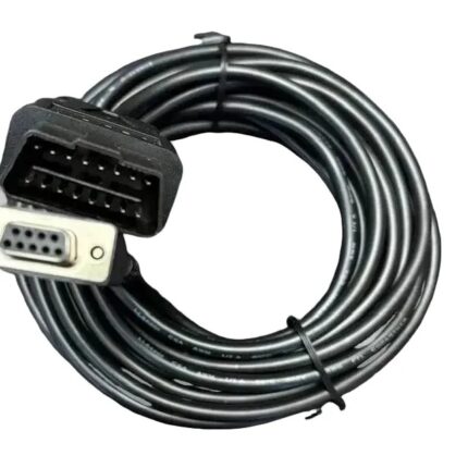
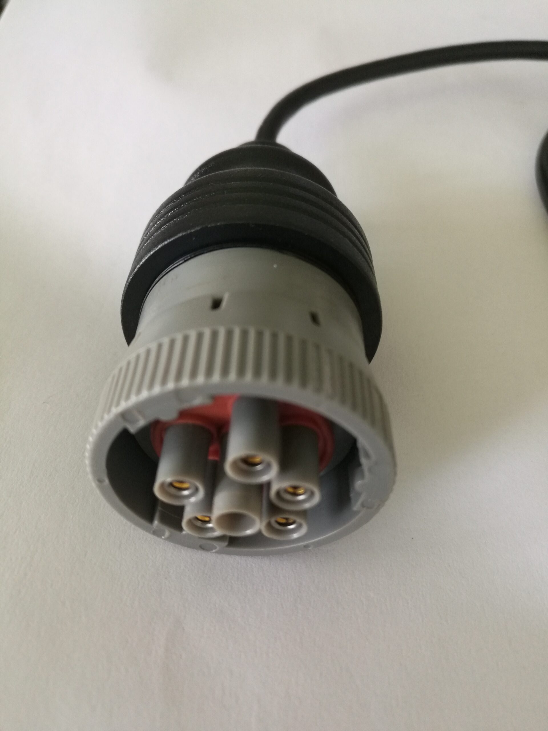
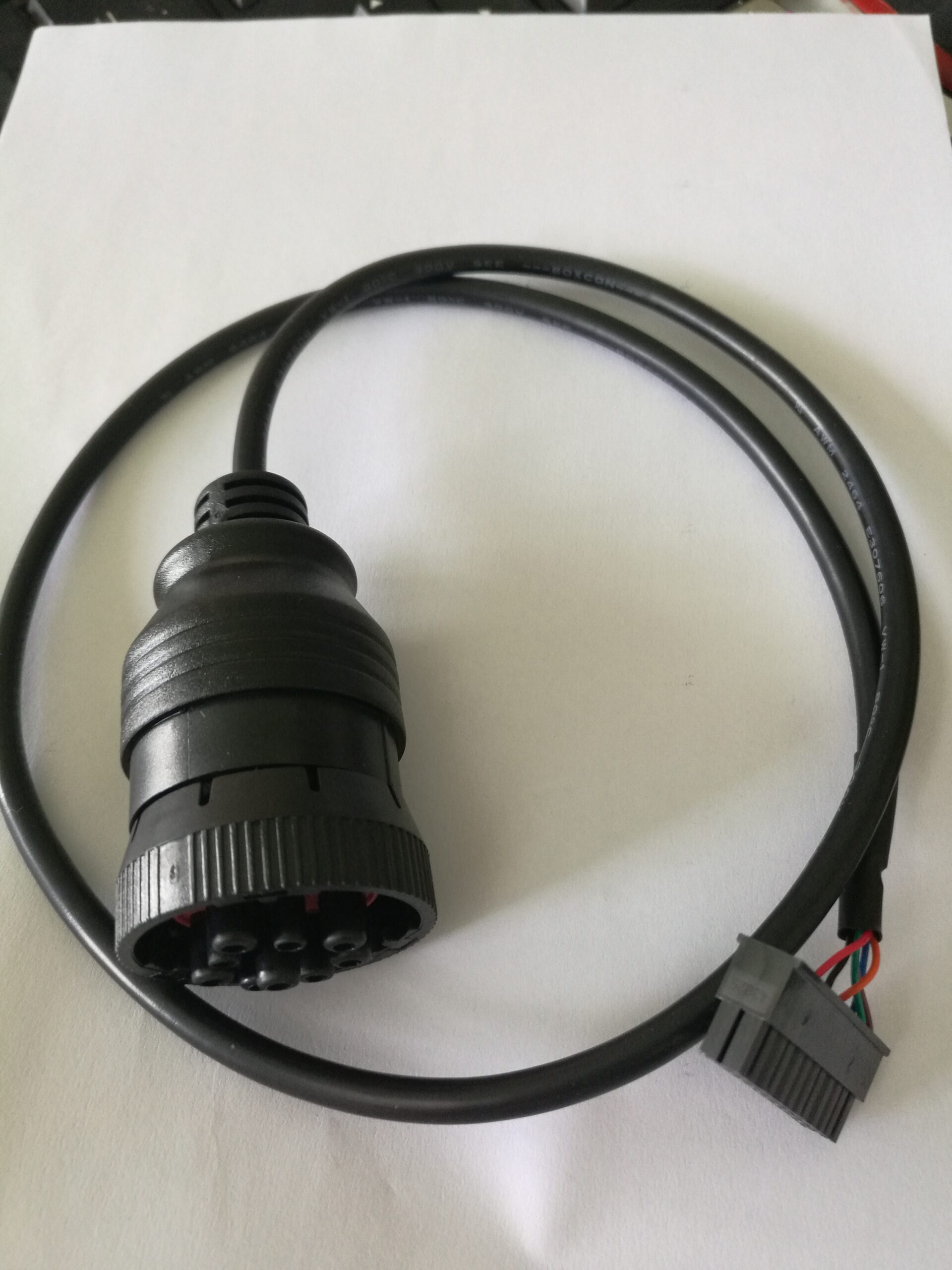
A heavy duty 9 pin cable with a 9-pin round industrial plug and a 14-pin 2×7 DIP bare end, for engine management diagnostics on trucks, marine diesel and heavy equipment benches. Verify the pinout against your service manual, since 9-pin assignments follow the engine maker rather than one specification.
Overview
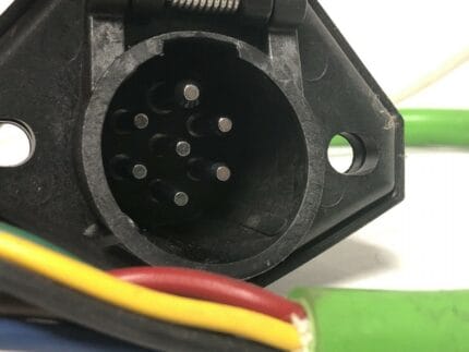
A heavy duty 9 pin cable is the diagnostic lead for vehicles and plant that do not have a J1962 port at all. One end is a round 9-pin industrial diagnostic plug, the other a 14-position 2×7 DIP bare end you terminate into a breakout box, a data logger or a bench harness. The round shell carries engine management, marine diesel, generator set and industrial engine traffic, and its coupling is a threaded coupling ring rather than the friction fit of a passenger car port. Here is the part that catches people out: the 9-pin assignment is not one specification. It follows the engine maker, so you verify against your service manual before you power anything up.
Key Specifications
| Cable Type | Heavy-Duty Industrial Cable |
|---|---|
| Connector A | 9-Pin Round Female (Red Insert) |
| Connector B | 14-Pin 2×7 DIP Bare End |
| Application | Heavy Equipment / Marine Diesel Diagnostics |
| Coupling | Threaded coupling ring |
| DIP pitch | 2.54 mm between pins, 7.62 mm between rows |
| System voltage | Stated per your drawing |
| Length | Stated per your drawing |
| Testing | 100% continuity and pinout check before packing |
Which 9-pin world are you actually in?
Four different things live behind that round shell, and they are not interchangeable. Two of them are published standards, one is a legacy pair of them, and the fourth is whatever the engine maker decided. The shell color is your fastest field identification, and the insert color on the receptacle is the second clue: on this build the insert is red, which is one of several maker conventions rather than a universal code.
| World | How to recognize it | What rides on the pins | Notes |
|---|---|---|---|
| J1939 Type 1 | Black shell, the older and still common assignment | CAN pair plus battery and ground, legacy J1708 pair alongside | Commonly quoted at 250 kbit/s on the primary pair |
| J1939 Type 2 | Green shell, the assignment most current heavy trucks use | CAN backbone pair plus a second channel or the legacy link | Commonly quoted at 500 kbit/s on the backbone pair |
| J1708 / J1587 | Older vehicles and a lot of industrial and marine engines | An RS-485 style pair, not CAN | Your CAN tool will sit silent on this network |
| OEM defined | Anything not matching the above, including many genset controllers | Whatever the maker documented | Build to the pinout you measure or the one your tool vendor publishes |
The nine cavities, one letter at a time
Positions are identified A through J, and there is no I, which trips people up the first time they read a pinout chart. The SAE J1939 assignment below is the common one; treat it as a starting point and confirm it against your machine before you trust it.
| Pin | Signal | Typical J1939 assignment | What you should verify |
|---|---|---|---|
| A | Battery negative | Ground | Continuity to the battery negative post |
| B | Battery positive | Unswitched 12 V or 24 V | The system voltage, and that it is fused |
| C | CAN high | Primary CAN pair | Which channel, and at what bit rate |
| D | CAN low | Primary CAN pair | Same channel as C |
| E | CAN shield | Shield ground | Whether it is tied at one end or both |
| F | Second pair or legacy | CAN 2 high, or J1708 high | Whether the legacy network is populated |
| G | Second pair or legacy | CAN 2 low, or J1708 low | Whether the legacy network is populated |
| H | OEM defined | Auxiliary or a second channel | Usually the one that varies most |
| J | OEM defined | Auxiliary or unused | Often unused; confirm before assuming |
Round 9-pin and J1962 are two different diagnostic worlds
Workshops that move between cars and heavy equipment carry both leads, and it is worth being clear about why one cable cannot cover both.
| Round 9-pin port | J1962 16-pin port | |
|---|---|---|
| Where it lives | Cab, engine bay or chassis, often exposed | Under the dash, inside the cabin |
| System voltage | 12 V and 24 V are both common | Predominantly 12 V |
| Coupling | Threaded ring or bayonet, locks under vibration | Friction fit, held by the socket shape |
| Protocols | J1939, J1708 / J1587, and maker-specific sets | ISO 15765 CAN, ISO 9141, J1850 and maker sets |
| Pinout | Follows the engine maker, not one standard | Allocated by protocol in SAE J1962, with OEM discretion on several pins |
| What breaks | Corrosion and vibration at the coupling | Strain relief and bent pins from footwell abuse |
Why the threaded coupling ring is not a detail
A diagnostic port on a truck, a marine engine or a generator set sits somewhere that shakes. A friction-fit plug works itself loose, and a loose diagnostic plug produces the worst kind of fault: intermittent, load-dependent, and never reproducible on the bench. The threaded coupling ring takes that failure mode off the table, provided you actually tighten it. Use your fingers and then a little more; a port that has been cross-threaded once will never hold properly again, so check the threads before you blame the cable.
Construction
- Round 9-pin female plug with the insert and keying you nominate, threaded coupling ring fitted.
- 14-position 2×7 DIP male header at 2.54 mm pitch, or flying leads if you prefer screw termination.
- Stranded copper conductors, cross section stated on your drawing.
- Shield and drain construction per your drawing, with the drain dealt with at the connector end.
- Overmolded strain relief at the plug, and a jacket chosen for oil, fuel and salt exposure.
How to specify your build
- The port – shell color, insert color, keying, and a photo of the receptacle.
- The pinout – from your service manual, or the one your tool vendor documents.
- The far end – 2×7 DIP header or stripped and tinned flying leads.
- System voltage, so the conductor sizing and jacket are right.
- Length, and whether the run passes a hot or moving part.
Typical applications for this heavy duty 9 pin cable
- Marine diesel diagnostics where the engine and the helm are in different compartments
- Generator set and industrial engine controllers on a test stand, alongside a DT connector pigtail harness
- Heavy equipment service vans carrying one lead for mixed plant, paired with a Type 2 green 9-pin J1939 cable
- Fleets that still run legacy networks, with the black 9-pin J1939 Type 1 adapter in the same kit
- Telematics installs that need a breakout point, next to a J1939 9-pin Y splitter
Workmanship and testing
For Heavy-Duty 9-Pin Industrial Diagnostic builds the line runs to IPC/WHMA-A-620 Class 3 under ISO 9001, terminating 32 to 12 AWG. continuity and pinout are tested on each Heavy-Duty unit before it is packed, and seal checking is quoted whenever an ingress rating is on the drawing.
RoHS and REACH declarations are provided per project together with the agreed test reports; the documentation scope is listed under certifications and compliance. If your drawing specifies a UL style, we build to that drawing and supply the UL reference with the shipment instead of substituting an equivalent. The molded body is shot on our own presses; material choice and bond behavior follow the process described under how we run the overmold press. More background: what changes on vehicle harness builds. Any tooling we cut for this part stays yours, maintained in our own tool room under your part reference.
Custom builds and ordering
Heavy-Duty 9-Pin Industrial Diagnostic prototype lots start from 1 to 50 pcs and ship in 3 working days; production requires 500 pcs and runs 14 working days after sample approval. Your part number and labeling go on OEM and ODM Heavy-Duty shipments, and we provide material certificates and first-article reports when asked. We hold 100 sets of mold tooling in house, so a standard body needs no tooling time and a new one adds about 10 working days.
Related heavy-duty diagnostic leads
- SAE J1939 OBD2 Diagnostic Cable, Type 2 Green 9-Pin
- Black 9-Pin J1939 Type 1 Adapter to OBD2 16-Pin Socket
- J1939 9-Pin Y Splitter Cable for ELD and GPS Trackers
- DT06 to J1939 Adapter Cable for Tractors and Excavators
- DT Connector Pigtail Harness, 2 / 3 / 4-Pin Sealed
Full range: automotive cable and wire harness.
Frequently Asked Questions
Is the 9-pin pinout standardized?
Partly. J1939 assignments are published and widely followed, but plenty of industrial and marine engines use the same shell for something else. Verify against your service manual before you rely on it.
Will this work on a 24 V system?
Yes, the build is quoted for the system voltage you state. Tell us whether it is 12 V or 24 V so the conductor sizing and the jacket match.
Can I have flying leads instead of the DIP header?
Yes. If your breakout box takes screw terminals, stripped and tinned conductors are usually easier to work with than a header.
My tool connects but reads nothing. Why?
Most often the network: a CAN tool on a J1708 port, or a Type 2 expectation on a Type 1 vehicle. Check the shell color, then check which pair carries the traffic.
| Cable Type | Heavy-Duty Industrial Cable |
|---|---|
| Connector A | 9-Pin Round Female (Red Insert) |
| Connector B | 14-Pin 2×7 DIP Bare End |
| Application | Heavy Equipment / Marine Diesel Diagnostics |
| Coupling | Threaded coupling ring |
| DIP pitch | 2.54 mm between pins, 7.62 mm between rows |
| System voltage | Stated per your drawing |
| Length | Stated per your drawing |
| Testing | 100% continuity and pinout check before packing |