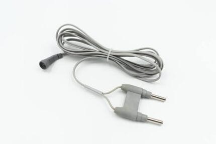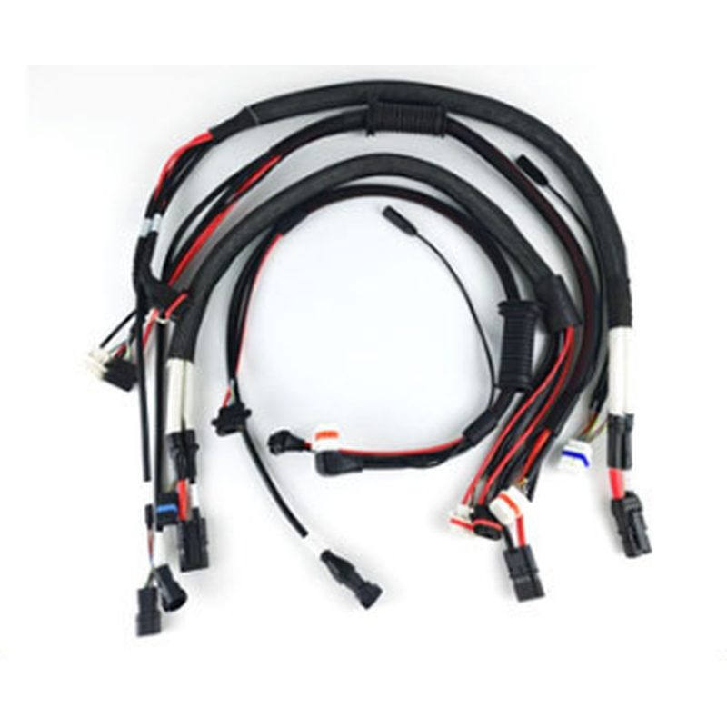
ESC Cable Assembly for Drone Speed Controllers, Built to Drawing
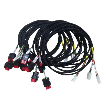
An ESC cable assembly gathers everything meeting at a speed controller into one loom: power input, three motor phase leads, throttle signal and telemetry return, built to your interfaces and labeled per branch.
Overview
An ESC cable assembly gathers everything that meets at an electronic speed controller into one loom: the DC input from the power distribution point, the three phase leads out to the motor, the throttle signal coming in from the flight controller, and the telemetry or tachometer path going back. Built as separate jumpers, those four functions become four things to route, four things to secure, and four things to get wrong during assembly. Built as one assembly, they become a single part number that goes on an airframe in one motion.
This is the part usually quoted when a program moves past prototype builds, because it converts a bench wiring job into a line item. We build it to your drawing: your interfaces, your lengths, your pinout, your labels. Send a schematic, a wire list, or a harness you are flying today and we will turn it into a documented part.
Key Specifications
The specification table on this page lists the configuration shown in the product photo. Conductor sizes, interface series, screen assignments and branch lengths are stated per build from your drawing, because all four are decisions you have already made on the bench.
What Sits Inside an ESC Cable Assembly
Four functions meet at a controller, and an assembly around it has to respect how different they are. The input pair carries the whole current the motor draws, so it is thick, short and made of high-strand wire. The output triplet carries the same current but switched, so it is noisy, benefits from being twisted, and wants to be kept away from anything sensitive.
The throttle and telemetry paths are the opposite kind of conductor entirely: milliamps, thin insulation, and hostile to being bundled alongside either of the first two. And if your controller emits a regulated output for servos or receivers, that rail has its own routing discipline, because sharing a return path with motor current is how people end up chasing intermittent resets in flight.
Handling all four in one loom means deciding where each one physically lives inside the bundle. It is not decorative neatness; the layout is the product.
Power Input Leads: Keeping the Bus Short and Thick
Input conductors are the ones that punish optimism. Published build guidance consistently places main battery leads around 10 to 12 AWG on mid-size multirotors and lighter for micro airframes, sized from continuous current rather than motor class, and it places controller input leads in a similar range. Every centimeter of that run adds resistance, and resistance turns into heat and lost throttle headroom at the exact moment you least want either.
So the input branch is built short, from high-strand tinned copper, terminated into the interface you specify, and strain relieved where it leaves the loom rather than at the solder joint. If your drawing gives us a target lead length, we build to it; if it gives us a battery position and a controller position, we will propose one.
Three Output Leads to the Motor
The output side is where the switching energy lives, and it is the part most builders twist and few explain. Twisting the three phase leads narrows the loop they radiate from, which measurably reduces what couples into neighboring signal wiring, video paths and magnetometers. This advice appears in essentially every serious UAV wiring guide for a reason — it costs seconds and removes a class of interference that is otherwise extremely annoying to diagnose.
We twist to the lay length you specify, or to a sensible default recorded against your part number. If your airframe already solves this by keeping the motor close to the controller, say so and we will shorten rather than over-engineer.
Throttle Signal and Telemetry Return Paths
Signal conductors belong to a different world. Typical signal runs in this configuration sit in the 26 to 30 AWG band, carry milliamps, and fail from being pulled rather than from being overloaded. They also fail from being misunderstood: if they run parallel to motor leads for any distance, they pick up exactly what is being switched a few millimeters away.
Two practices fix most of it. Route signal branches physically away from power branches inside the loom or split them into breakouts that leave in different directions. And where the signal is differential — CAN pairs, some telemetry links — keep the pair twisted to the end, because that twist, not the shield, is what does most of the work.
BEC Taps and Where They Cause Trouble
Where an ESC cable assembly carries a regulated output to feed a receiver or servo bus, the return path matters more than the supply. Shared returns let switching noise find its way into logic rails, and the symptom is rarely obvious: brownouts appear at high throttle, disappear on the bench, and get blamed on everything except the harness.
The fix is routing rather than expensive material. Keep the regulated branch on its own pair, do not share its ground with motor current, and keep any high-draw device off it entirely. On the manufacturing side that means separate pairs, defined breakouts, and labels that make the separation obvious to whoever wires the airframe.
Separating Power from Signal in One Loom
Putting power and signal in one part number does not mean running them side by side. A well-built ESC loom keeps them as distinct branches that leave the controller in different directions, or groups the signal pair with its own braid so it has a defined return path that is not the nearest motor lead.
Shielding is assigned per path rather than globally. Adding a screen everywhere adds cost and weight and does nothing useful on a twisted power triplet, while leaving it off a long telemetry run invites exactly the interference nobody wants to chase. Tell us which paths are sensitive, or let us propose an assignment and explain it.
Connector Choices on the ESC Side
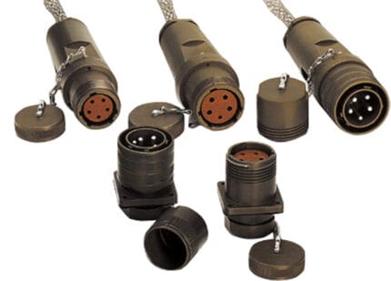
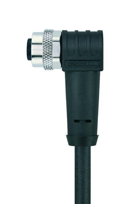
Interfaces here divide neatly into three groups: high-current inputs and outputs, compact keyed signal housings, and direct solder terminations. The first wants contact area and retention; the second wants polarization so nobody inserts it backwards; the third wants strain relief because a solder joint to a board is a mechanical part as much as an electrical one.
You do not have to learn our catalog — there is not one here. Name the series on your drawing, send a sample, or describe the pin pitch and count, and we build to that interface with contacts rated for the current you actually run.
Typical Applications
On a compact multirotor, this assembly is usually built around a four-in-one controller: one input pair, four output triplets, one signal branch, all cut to specific arm lengths so the build goes together in one pass on the line.
On larger multirotor and VTOL platforms the same idea spreads out. Individual controllers sit at the motors, so each assembly gets longer input leads, thicker conductors, and often a defined service loop so the unit can be removed for maintenance without cutting anything.
Industrial inspection, mapping and survey platforms add documentation requirements — serialized labels, recorded pull values, continuity records attached to the batch — which we quote into the part rather than treating as an afterthought.
Agricultural and long-endurance airframes add fluids and cleaning cycles, which pushes jacket choice toward materials that shrug off the chemistry and, where the controller sits outside a sealed bay, toward sealed transitions at every exit.
Specifying Your ESC Cable Assembly
A complete request fits in a short email. Send the current per phase and at the input, the pinout of each interface, the length of every branch, any signal pair that must stay twisted or screened, the labels you need printed, and the documents you expect back. Add which compliance documents your purchasing team requires, and we will quote them rather than discover them.
If none of that is written down, send the harness off an airframe you already trust. Reverse-engineering a sample into a drawing is routine work here and usually produces a better part than a specification written from scratch, because the sample already reflects decisions that survived flight testing.
Custom Builds and Ordering
Every assembly is built to order. Prototypes start at one; production pricing begins at 500 pieces. Tooling for any molded breakout is cut in our own tool room and belongs to your program, so repeat runs start from an existing tool rather than a new setup.
Packaging and Shipping
Looms ship bagged by part code, coiled rather than folded, with labels protected from abrasion. Records accompany production batches when you ask for them at quotation rather than after packing.
Quality and Compliance
Every branch is continuity tested, every keyed housing is checked for pin position against your drawing, and each assembly is inspected to the workmanship class agreed at quotation. First article inspection precedes production, so the agreement is against a physical part rather than a description.
Material declarations against RoHS and REACH are issued per project, alongside the dimensional and electrical reports agreed at quotation; see certifications, compliance and material declarations. Where your drawing names a UL style or another approval, the build follows your drawing and ships with the supporting document rather than a claim of our own. Where the build calls for sealed exits, they follow the insert, gasket and overmold-bond method described under IP67 and IP68 sealing structures. Related reading: prototypes and first article inspection.
Frequently Asked Questions
Do you supply to a pinout I define? Always. We do not substitute an interface for the one your controller and receiver already use.
Can signal and power really share one harness? Yes, provided they occupy separate branches that leave in different directions, and sensitive pairs get their own twist and where needed their own screen.
Can you work from the harness I already fly? Yes, and it is the most common way these programs start. One sample is usually enough to produce a drawing.
What about the connector series on my board? Give us the series name or a sample. We build to the interface rather than steering you toward a different one.
How short should the input leads be? Shorter than feels necessary. Length there buys nothing and costs current headroom.
Can every branch be labeled? Yes — printed sleeves, flags on signal branches, or serialized labels for asset-tracked fleets.
What is the minimum order? One prototype set; production pricing from 500 pieces.
How fast do you quote? About three working days from a complete drawing or a received sample.
Related Cable Ranges
Start from the drone and UAV cable assembly overview, or read how noise gets into a harness in weight, vibration and EMI in a drone cable.
Adjacent parts on the same airframe: the drone motor cable assembly that continues downstream of this loom, the flight controller wiring harness that feeds the throttle signal into it, and the drone battery power harness upstream.
The full custom wire harnesses range covers other industries built to the same process.
| Product type | ESC cable assembly: input power, motor phase leads, throttle signal and telemetry in one loom |
|---|---|
| Build basis | Built to your drawing, wire list or a harness you already fly |
| Input branch | Sized from your input current; short by default to protect headroom |
| Output branch | Three phase leads per motor, twisted where specified |
| Throttle signal | Fine-gauge signal conductor, routed clear of power branches |
| Telemetry return | Tachometer or data return pair kept twisted to the endpoint |
| Regulated tap | Separate pair with its own return where your controller supplies one – confirm per build |
| Conductor range | 32 to 12 AWG, assigned per branch rather than one size throughout |
| Screening | Assigned per path; not applied by default – confirm per build |
| Connectors | Bullet, keyed low-pitch housing or solder terminations per your BOM |
| Marking | Printed sleeves or flag labels per branch; serialized tags for tracked fleets |
| Tooling | Tooling cut in our own tool room; 3,000 plus tooling sets built since 2012 |
| Workmanship | IPC/WHMA-A-620 Class 3 under ISO 9001 |
| Testing | 100% continuity against your pinout; branch-by-branch verification before packing |
| Typical applications | Four-in-one controller builds, heavy-lift multirotors, VTOL propulsion units, industrial inspection and mapping platforms |
| Order quantity | Prototype 1 to 50 pieces; production from 500 pieces |
Related products