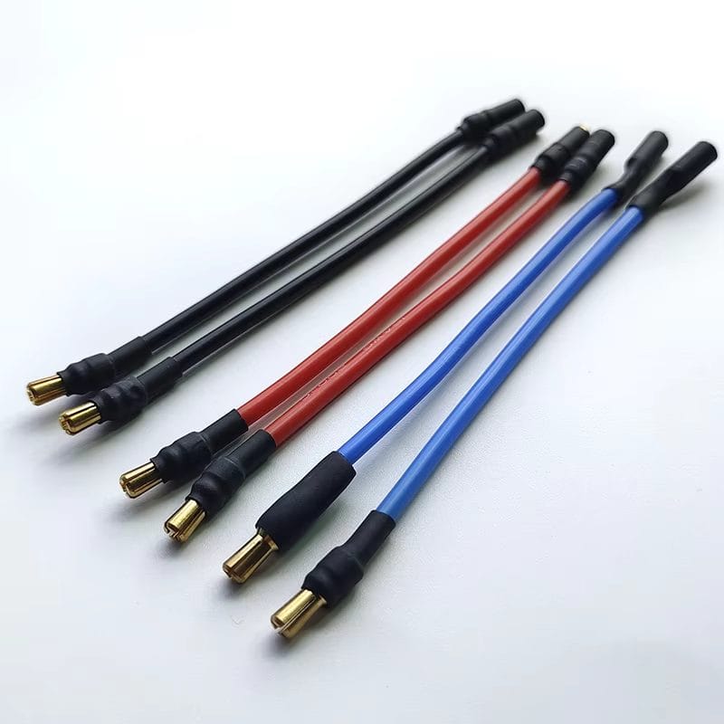
Drone Motor Cable Assembly, Three-Phase Motor Leads Built to Drawing
A drone motor cable assembly is the set of three leads between a brushless motor and its speed controller, built to your gauge, length and phase colors so the leads stop being the first thing that fails in service.
Overview
A drone motor cable assembly is the short, unglamorous set of three leads between a brushless motor and its speed controller, and it is asked to do more than its length suggests. Each lead carries the full phase current, switched tens of thousands of times a minute; each sits inside an arm that vibrates at propeller frequency for the whole flight; and none of the three can be allowed to work loose, chafe through, or radiate enough noise to disturb the compass a few centimeters away.
We build these to your drawing, which in practice means you decide the gauge, the strand count, the phase colors, the length to each arm and the termination at each end. You can send a dimensioned drawing, a wire list, or simply a photographed sample of what you are using now. There is no stock part to pick from, because the useful version of this product is the one that matches the motor, the controller and the arm you already committed to.
Key Specifications
The specification table on this page lists the configuration shown in the product photo. Every line there is what we can build routinely; the values that depend on your platform — gauge, length, strand count, termination series — are stated per build against your drawing.
What a Drone Motor Cable Assembly Has to Survive
A motor lead sees three loads at once, and only one of them is electrical. The first is current: whatever the controller pulls at full throttle, per phase, continuously enough to heat the conductor. The second is mechanical: the airframe transmits propeller and rotor unbalance into the arm, and the arm hands it to every solder joint along the route. The third is electrical again, but in the other direction — the cable is also an antenna radiating sharp-edged switching noise into whatever sensitive wiring runs next to it.
Assemblies designed for this get three things right. The conductor is sized so rise stays inside the jacket rating at your real burst current, not at some nominal figure. The stranding is fine enough that flexing does not fatigue copper at the crimp exit. And the lead is strain relieved at both ends so that frame movement is absorbed by designed slack rather than by the solder joint, which is the single most common failure we are asked to fix.
Why Three-Phase Leads Fail Before the Motor Does
Motor windings are potted, varnished and supported by a bearing. The leads leaving them are none of those things. Look at a failed arm and the break is rarely mid-cable — it is within a few millimeters of the solder pad or the crimp barrel, where conductors stop being supported and start being flexible. The joint becomes the flex point, work hardens, and then the wire goes.
The second failure we see is thermal and it is quieter. An undersized phase lead does not melt dramatically; it runs warm, the jacket stiffens, the joint above it oxidizes, resistance climbs, and the lead runs warmer still. This is why sizing deserves the small effort it takes: a lead chosen for the peak number rather than the average one costs a few grams and removes a whole class of field failure.
The third is routing, and it is free to fix. A bundle that leaves the arm and immediately runs alongside compass or GNSS wiring couples the noisiest cable in the airframe into the most sensitive one. Separating those two routes costs nothing and is worth more than most upgrades people spend money on.
Choosing the Gauge for Your Drone Motor Cable Assembly
Gauge selection starts from measured current, not from motor size. For reference, published build guidance across hobby and professional UAV platforms converges on a narrow set of ranges: main battery leads typically land at 10 to 12 AWG, controller-to-motor phase leads at roughly 14 to 18 AWG, regulated 5 V rails around 20 to 22 AWG, and pure signal runs at 24 to 30 AWG. Those numbers move with platform class — micro airframes below 250 g run thinner wire at far lower voltage, while heavy-lift platforms run thick phase leads at bus voltages in the tens.
Pick your position inside that range from two numbers you can measure: sustained current per phase and one-way lead length. Then check voltage drop across the run, because long thin motor leads do not just heat — they steal torque at exactly the moment throttle is highest. If you already fly the platform and can tell us what the current draw peaks at, we will size the conductor and confirm it on the drawing before a single lead is cut.
Strand Count, Stranding and Why Stiffness Matters
Two leads of the same gauge can behave completely differently in an arm. The difference is stranding: many fine strands flex repeatedly without accumulating damage, where few coarse strands work harden quickly and then crack. This is the reason high-strand tinned copper silicone wire became the default in this application rather than PVC hookup wire of the same current rating.
Tinning is not cosmetic. It keeps every strand solderable months after the wire left the reel and slows the surface oxidation that raises joint resistance over time. Specify the strand count if you care about it; if you do not, we will propose one matched to your bend radius and vibration environment and record it against the part number so repeat orders match.
Phase Order, Color Code and Termination
A brushless motor is driven with three phase-shifted currents, and reversing direction is done by swapping any two of the three leads rather than anything inside the motor. That single fact drives how we build the assembly: if phase identity is not recoverable in the field, a five-minute direction fix becomes a rework job.
So the three leads are identified the way you want them identified — distinct colors, printed numbers on the jacket, or numbered heat-shrink markers at both ends. Where a phase sequence is specified on your drawing, we build to it and verify it electrically before packing; where it is not, we ship a documented, consistent convention so a technician can reason about the harness without a diagram.
Both ends are built to whatever the hardware expects: bullet terminations to a dimension you name, bare tinned ends for direct soldering into controller pads, crimped contacts into a keyed housing, or overmolded transitions where the arm exit needs strain relief and sealing in one part. Nobody outside your engineering team needs to invent anything here — the termination series on your drawing is the termination we build.
Construction and Materials
The default insulation is high-strand tinned copper silicone rated to 200 °C, which is what most motor and battery leads in this application already use and what most people already own a soldering setup for. Silicone survives the iron, does not retract when a joint takes a second longer than planned, and stays flexible at low temperature instead of stiffening into a lever.
Where the duty calls for it we build the same geometry in PTFE or FEP insulation — thinner walls for tight routes, higher temperature margin, or better resistance to fuels and solvents in long-endurance and agricultural airframes. Abrasion sleeves, glass-fiber or braided, go over the lead where it crosses a carbon edge; heat-shrink strain relief sits at every exit where the conductor stops being supported.
Twisting and Electromagnetic Separation
Twisting each motor’s three phase leads along their length is a one-minute action with a measurable payoff: it reduces the loop area the switching current radiates from, so less of that energy reaches signal wiring, video paths and magnetometers. Build guidance across the field is consistent on this point, and it is why twisted triplets ship as standard when you ask for them.
The rest of electromagnetic discipline is routing rather than construction. Keep the power leads and the signal runs physically separated along the arm, give the compass and GNSS leads their own route away from the phase leads, and avoid running either along the length of the other for longer than you have to. We cannot see your airframe, but we can build to lengths and breakouts that make the clean route the natural one.
Typical Applications for This Drone Motor Cable Assembly
On a five-inch freestyle or cinewhoop airframe the assembly is usually a short triplet from a four-in-one controller out to each arm, sized around 16 AWG equivalents, with all three leads cut to equal length so the build stays symmetrical and the spares pool stays small.
On heavy-lift multirotors the same part becomes much more interesting: longer arm runs, thicker phase conductors, larger bullet interfaces, and usually a requirement for documented torque or pull values on every termination because the consequence of a lead letting go is the airframe.
Industrial inspection platforms add a different constraint. Vibration spectra differ from hobby frames, flights are longer, and the operator usually wants every lead identified and logged against a serial number so that maintenance records survive the asset rather than the technician.
Agricultural spraying airframes add chemistry. Fuel, fertilizer and cleaning agents reach the wiring, which is where FEP insulation and sealed transitions earn their cost.
Fixed-wing and VTOL hybrids ask for a mixture: propulsion leads sized like multirotor leads, control-surface servos on their own lighter branch, and a clear separation between the two that survives someone opening the fuselage in the field.
Specifying Your Build
A useful request to us is short. Tell us the current per phase at full throttle, the one-way length to each motor, the interface at each end (a series name, or a sample you can post), your preferred jacket, and whether the three leads should be twisted, sleeved or left plain. Add the documents you need back — continuity records, pull-force data, material declarations — and we will price them into the quote rather than discovering them later.
If none of that exists yet, send the motor and controller you are building around and describe the airframe. Most customers start from a sample they are already flying, which is usually the fastest path to a part number.
Custom Builds and Ordering
Every drone motor cable assembly here is built to order. Prototype quantities run from a single set upward, which is where most programs start; production pricing begins at 500 pieces. Tooling for any molded part is cut in our own tool room and belongs to your program, so a repeat order years later starts from the same tool rather than a new quotation exercise.
Packaging and Shipping
Assemblies ship bagged and labeled by part code, coiled rather than folded, so nothing takes a set that will not relax. Test reports can accompany production batches on request.
Quality and Compliance
Every assembly is continuity tested and polarity-verified before packing, and every termination is inspected against the workmanship class agreed at quotation. Prototype approval precedes production tooling, so nothing is sealed before it is verified against your drawing.
Material declarations against RoHS and REACH are issued per project, alongside the dimensional and electrical reports agreed at quotation; see certifications, compliance and material declarations. Where your drawing names a UL style or another approval, the build follows your drawing and ships with the supporting document rather than a claim of our own. Where the build calls for a sealed arm exit, it follows the insert, gasket and overmold-bond method described under IP67 and IP68 sealing structures. Related reading: prototypes and first article inspection.
Frequently Asked Questions
Is there a stock drone motor cable assembly, or is everything custom? Everything is built to order. The variable—gauge, length, termination series—is exactly what makes the part fit your airframe.
Can you match a sample I am already flying? Usually yes, and it is generally faster than writing a fresh specification. Post one set and we will reverse-engineer the construction into a drawing.
Which termination should I choose? Whatever your controller and motor already use. If you are choosing freely, bullet terminations accept repeated disconnection and stripping; direct soldering is lighter and has fewer interfaces to fail.
Do I need to specify phase order? Only if it matters to your assembly process. Otherwise we ship a documented, consistent convention so a technician can swap any two leads to reverse rotation.
What if my phases need different lengths? Fine. Give us the length per lead on the drawing and we build to it, including mixed terminations within one assembly.
What does the prototype run look like? A small set built from your drawing or sample, inspected and shipped with records, so you can fly it before committing to production.
Can you supply wire only? We build assemblies. If you need cut, stripped and pre-tinned leads in bags rather than terminated sets, that is still an assembly order and quoted the same way.
How long does a quote take? Roughly three working days from a complete drawing or sample.
Related Cable Ranges
See the wider picture in the drone and UAV cable assembly overview, or read how weight, vibration and EMI shape these decisions in weight, vibration and EMI in a drone cable.
Sibling parts on the same airframe: the ESC cable assembly that feeds these leads, the drone battery power harness upstream, and the lightweight UAV wire harness for avionics bays.
Browse the full custom wire harnesses range for other industries.
| Product type | Drone motor cable assembly: three phase leads, speed controller to brushless motor |
|---|---|
| Conductor range | 32 to 12 AWG; gauge stated per build from your measured phase current |
| Typical build | Three equal-length leads per motor, cut to the length you state |
| Stranding | High-strand tinned copper – confirm per build |
| Insulation | Silicone rated 200 C standard; PTFE or FEP on request – confirm per build |
| Phase identification | Distinct colors, printed numbers or heat-shrink markers per your schedule |
| Termination at motor | Bullet connectors, solder pads, keyed housing or the series you name |
| Termination at controller | Pre-tinned or bare ends, or the same series, per your drawing |
| Twisting | Three leads twisted as one bundle where you specify it |
| Strain relief | Heat-shrink at every exit; molded transition where the arm needs sealing |
| Length tolerance | Stated per drawing and recorded against the part number |
| Tooling | Mold built to your geometry; molds cut in our own tool room belong to your program |
| Workmanship | IPC/WHMA-A-620 Class 3 under ISO 9001 |
| Testing | 100% continuity and polarity check; pull-force verification available per batch |
| Typical applications | Multirotor and VTOL propulsion, FPV and cinewhoop airframes, heavy-lift platforms, agricultural sprayers, fixed-wing rotor lifts |
| Order quantity | Prototype 1 to 50 pieces; production from 500 pieces |
Related products