Flight Controller Wiring Harness Built to Your Peripheral Map
A flight controller wiring harness consolidates every lead reaching the controller into one part: outputs, serial peripherals, sensor buses and receiver lines, built to your pinout with keyed housings and labeled breakouts.
Overview
A flight controller wiring harness consolidates every lead that reaches the controller into one part: servo-style outputs, serial peripherals, bus runs to sensors, receiver connections, sometimes a camera control or buzzer line. Built as individual jumpers, those thirteen or fourteen connections are thirteen or fourteen chances to misroute one during assembly, and thirteen or fourteen things to fault-find in the field. Built as one harness, they become a single part number that plugs in once and either works or does not.
We build these from your peripheral map. You tell us what connects to the controller, which interface each device uses, and what each connector looks like at the far end; we resolve that into a loom with defined branches, keyed housings, labeled breaks and a twist or screen where the signal actually needs one.
Key Specifications
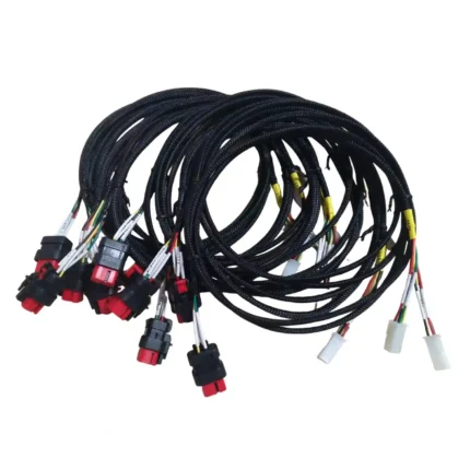
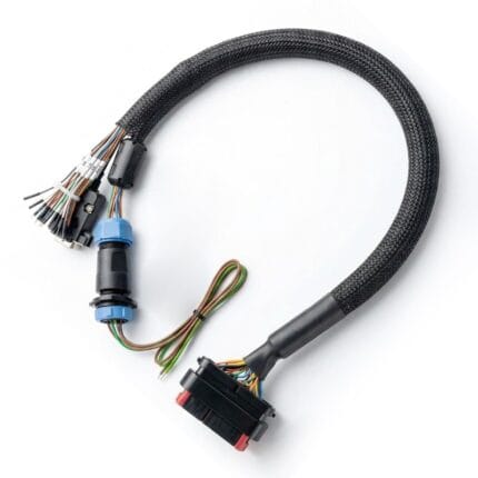
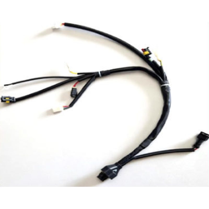
The specification table lists the configuration shown in the product photo. Every variable that matters here — pinout, pitch, branch length, conductor size per branch, labeling scheme — is set by your peripheral map and recorded against the part number.
Why One Harness Beats a Bundle of Jumpers
The obvious argument is assembly time, and it is real: one part goes on faster than fourteen. But the reasons that matter over a production run are less obvious.
The first is misrouting. A keyed housing can only go where it fits, whereas a set of identical loose leads can go anywhere someone is in a hurry. When the interfaces are physically different — and they are, once you commit to polarized connectors — assembly errors stop being possible rather than merely unlikely.
The second is length discipline. Every loose jumper is bought long enough to be re-routed, and the spare length has to live somewhere in the airframe. A harness is cut to the route, so the excess disappears from the build and from the weight budget.
The third is failure isolation. A harness with labeled breaks can be probed at known points, so a suspect connection takes minutes to identify instead of requiring the airframe to come apart.
Reading Your Peripheral Map
Controllers speak several languages, and each has a preferred way to be wired. Output channels carrying servo-style pulses are square-wave timing signals — low current, tolerant, and usually the least demanding branch in the loom.
Serial peripherals are different. A bus-heavy airframe — receiver, GNSS module, telemetry radio, maybe a companion computer — runs several point-to-point serial links, and each one needs its transmit and receive lines to land correctly at both ends. Get that wrong and the device simply does not answer, which is a confusing failure if the harness is undocumented.
Then there are shared buses. Short-run sensor buses carry clock and data lines to magnetometers, barometers and airspeed sensors; longer differential bus runs — increasingly the default for modern peripherals — have their own rules about pair twist and termination that your drawing should state. Finally there is the analog layer: battery voltage sense, current sense, sometimes an RSSI input, where a shared return through motor current quietly corrupts everything downstream.
Pinout Discipline: Keyed Housings and Cross-Over Risk
Most returns the industry sees happen because of one sentence in a specification rather than because of manufacturing. Two connectors with the same pitch, the same pin count and completely different pin assignments are visually identical, and a harness that assumed the wrong one will assemble perfectly and then not work.
So we treat the pinout as the drawing critical provision. Confirm the series and complete designation, the pin pitch and count, which end is plug and which is receptacle, the supply voltage on the harness, each pin function, whether transmit and receive need to cross between the two ends, and which way the housing latches.
Where two interfaces on your map are physically interchangeable but electrically different, we either change the housing, the keying or the labeling so they cannot be swapped. That is a manufacturing decision made to prevent an assembly error, and it is worth asking for early.
Gauge by Branch
A harness is not one gauge. Published build guidance across hobby and professional UAV platforms is consistent: signal branches typically fall around 26 to 30 AWG, regulated power rails around 20 to 22 AWG, and anything carrying propulsion current is sized from measured draw. Fine-gauge wire is not automatically better — too thin lacks mechanical strength, too thick adds weight and puts sustained bending load on solder joints.
Where one branch carries real current — a companion computer supply, a servo bus feeding several actuators — we step the branch up and, if your drawing calls for it, give that pair its own return rather than sharing one with signal branches. That single decision eliminates a family of intermittent resets that otherwise get blamed on firmware.
Shielding and Twisting Assigned per Path
Assigning a screen to every conductor is a way to spend money and grams without buying performance. A twist does most of the useful work on a differential pair. A screen earns its cost on a long low-level run routed near propulsion current, on GNSS and magnetometer leads, and on anything where a captured shield connection is part of your drawing.
So each path gets what it needs and nothing more: twisted pairs for serial and bus runs, screening on the few genuinely sensitive paths, plain fine-gauge wire on output channels where there is nothing to protect against. We will state what we propose and why, and change it if your testing says otherwise.
Labeling and Serviceability
Peripheral counts are going up, not down, and identification is what keeps a dense stack maintainable. Options here are printed sleeves at every breakout, flag labels on serial branches, unique identifiers per harness for asset-tracked fleets, or a simple color convention that matches your existing looms.
Whatever you pick, we recommend it be documented on the drawing. The value of a labeled harness is entirely in someone else being able to trust the label months later without the build notes.
Typical Applications for This Flight Controller Wiring Harness
On a survey or mapping airframe, the harness usually carries output channels, a GNSS and magnetometer branch, rangefinding sensors, a telemetry link and a companion computer supply — five or six protocols in one bundle, which is exactly where per-path assigning pays off.
On industrial inspection platforms the same airframe adds payload control — gimbal stabilization, camera trigger, lighting — and the harness becomes the boundary between flight-critical wiring and mission wiring, usually with a defined connector at that boundary so the payload can be swapped.
On VTOL and hybrid platforms the controller drives both rotors and control surfaces, so the harness carries output channels for servos and for rotor units simultaneously, with current-carrying branches that are visibly different from the signal ones.
On agricultural spraying platforms, the problem set is the number of branches plus fluid exposure, so the harness tends toward sealed branches and heavy-labeled breakouts that survive washing down.
Finally there are training and education airframes, where the requirement is different again: harnesses that can be unplugged and reinstalled many times, with labels that let a student work through the system without a diagram.
Specifying Your Harness
Send the peripheral list with the interface each device uses, the connector identification at the device end, required branch lengths, and labeling you want printed. Add the mechanical context if you can — where the controller sits, where each device sits, what has to route around — because that decides the practical sequence of the loom.
Tell us what testing you expect and what compliance documents your organization requires, and we will quote those into the part rather than negotiate them later. If the map exists only as a working prototype, that is a fine starting point; we will reverse-engineer it into a drawing and hand you back the documentation.
Prototyping This Flight Controller Wiring Harness
Prototype sets are built from the drawing, continuity tested against the pinout, and labeled as agreed. Anything that has to change is changed on the drawing first, so the second article is built to a corrected document rather than to a verbal note.
Production begins once the sample is approved. Because the tooling for any molded part belongs to your program, a repeat run later picks up where the last one left off, and each flight controller wiring harness ships with the same pinout and the same labels.
Custom Builds and Ordering
Every harness is built to order. Prototypes from one piece; production pricing from 500 pieces. Mixed configurations within one order are fine where the drawing supports it.
Packaging and Shipping
Harnesses ship bagged by part code, coiled rather than folded, with labels protected. Test records accompany production batches where agreed up front.
Quality and Compliance
Every branch is continuity tested against your pinout before packing, every keyed housing is inspected for pin position, and each assembly is inspected to the workmanship class agreed at quotation. Because the pinout is the critical feature here, it is verified electrically rather than visually.
Material declarations against RoHS and REACH are issued per project, alongside the dimensional and electrical reports agreed at quotation; see certifications, compliance and material declarations. Where your drawing names a UL style or another approval, the build follows your drawing and ships with the supporting document rather than a claim of our own. Where the build calls for sealed exits, they follow the insert, gasket and overmold-bond method described under IP67 and IP68 sealing structures. Related reading: prototypes and first article inspection.
Frequently Asked Questions
Can you build to a controller pinout I give you? Yes. That is the whole point of this part; we do not substitute our own pinout for yours.
What if two of my interfaces look identical but differ electrically? We change keying, housing or labeling so they cannot be swapped. Ask for this early — it is easier than discovering it later.
Do I need shielding on every path? No. Twisting handles most differential runs; screening earns its cost on a small number of genuinely sensitive paths.
Can different branches use different gauges? Yes, and they usually should. Signal, regulated power and propulsion current do not belong on the same conductor size.
How many connectors can one harness carry? Whatever your peripheral map needs. There is no practical ceiling below the point where the loom stops being serviceable, and we will say so if we think you have passed it.
Can every breakout be labeled? Yes — printed sleeves, flags, or serialized tags for fleets.
What is the minimum order? One prototype; production pricing from 500 pieces.
How long does a quote take? About three working days once the peripheral map and interfaces are known.
Related Cable Ranges
The drone and UAV cable assembly overview places this harness inside the full airframe loom set.
Neighbors on the same airframe: the ESC cable assembly, the drone motor cable assembly and the lightweight UAV wire harness for larger airframes.
Browse the wider custom wire harnesses range.
| Product type | Flight controller wiring harness: one part covering every connection to the controller |
|---|---|
| Build basis | Built to your peripheral map, pinout and interface callouts |
| Interfaces supported | Servo-style outputs, serial peripherals, shared sensor buses, differential bus runs, analog sensing |
| Conductor range | 32 to 12 AWG, assigned per branch from current and length |
| Branch count | Stated per drawing; no practical ceiling below serviceability |
| Return paths | Separate returns for current-carrying branches where your drawing requires it |
| Twisting and screening | Twisted pairs for serial and bus runs; screening only where the path needs it |
| Labeling | Printed sleeves at every breakout, flag labels, or serialized tags |
| Keying | Housings chosen or re-keyed so electrically different interfaces cannot be swapped |
| Tooling | Molds cut in our own tool room belong to your program, so repeat runs match |
| Workmanship | IPC/WHMA-A-620 Class 3 under ISO 9001 |
| Testing | 100% continuity verified electrically against your pinout before packing |
| Typical applications | Survey and mapping aircraft, industrial inspection platforms, VTOL designs, agricultural airframes, training airframes |
| Order quantity | Prototype 1 to 50 pieces; production from 500 pieces |