OBD2 16-Pin Pigtail Harness
An OBD2 16-pin pigtail harness is a build-to-print assembly with a 16-position diagnostic connector on one end and open wire ends on the other. Choose an overmolded plug, an assembled housing or a female socket with flying leads; pinout, conductor count, jacket, length and far-end termination are set on the approved drawing. All electrical ratings and pricing are confirm per build or confirm per RFQ.
Overview
An OBD2 16-Pin Pigtail Harness is a build-to-print cable assembly that puts a 16-position diagnostic connector on one end and leaves the other end as individual conductors for your equipment. We supply the interconnect: the connector and its contact insert, the jacketed multiconductor cable, the rear strain relief and the far-end terminations shown on your drawing. Depending on the build, that connector end can be an overmolded plug, an assembled housing or a female socket with flying leads. We do not publish electrical ratings, protocol support, vehicle compatibility or approval claims for this product; those belong to the equipment design and are confirm per build or confirm per RFQ.
Read the OBD2 16-Pin Pigtail Harness as a construction description rather than a fixed catalog part. Two leads built around the same 16-position housing can differ in gender, keying, pinout, conductor count, jacket, length and rear sealing, and each difference changes what ships. The sections below explain the connector geometry, why open wire ends need a drawing, and what we need from you to quote a build.
What an OBD2 16-Pin Pigtail Harness Includes
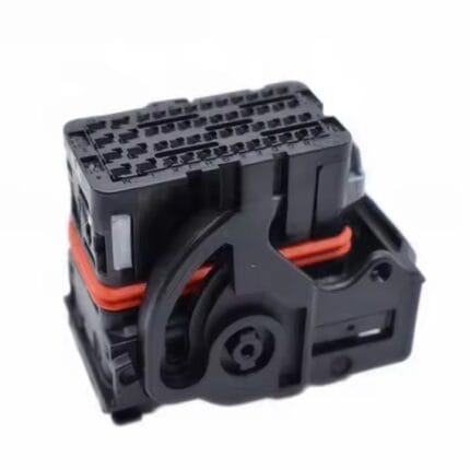
Four elements are joined in one assembly. First is the connector body with its 16-position contact insert, available as a male pin plug or a female socket. On an assembled housing the insert is retained by a colored terminal position assurance piece and a secondary lock, and the shell clips or a rear backshell hold the housing together. Second is the contact set itself, terminated to the conductors by crimping or soldering as the drawing requires. Third is the jacketed multiconductor cable, cut to length and marked to the wire color code. Fourth is the rear transition: an overmold, a backshell or an adhesive-lined sleeve that carries strain from the flexible lead into the rigid housing so a pull on the cable loads the jacket instead of the individual terminations.
The far end is deliberately open. Leads can be cut flush, stripped, tinned, fitted with crimped terminals, or terminated into a connector you specify. That flexibility is the reason this build exists, and it is also the reason we ask for a drawing rather than a verbal description. No brand name is claimed for the finished lead, and no electrical or environmental value is asserted without a corresponding document, confirm per build.
The 16-Position Diagnostic Connector Geometry
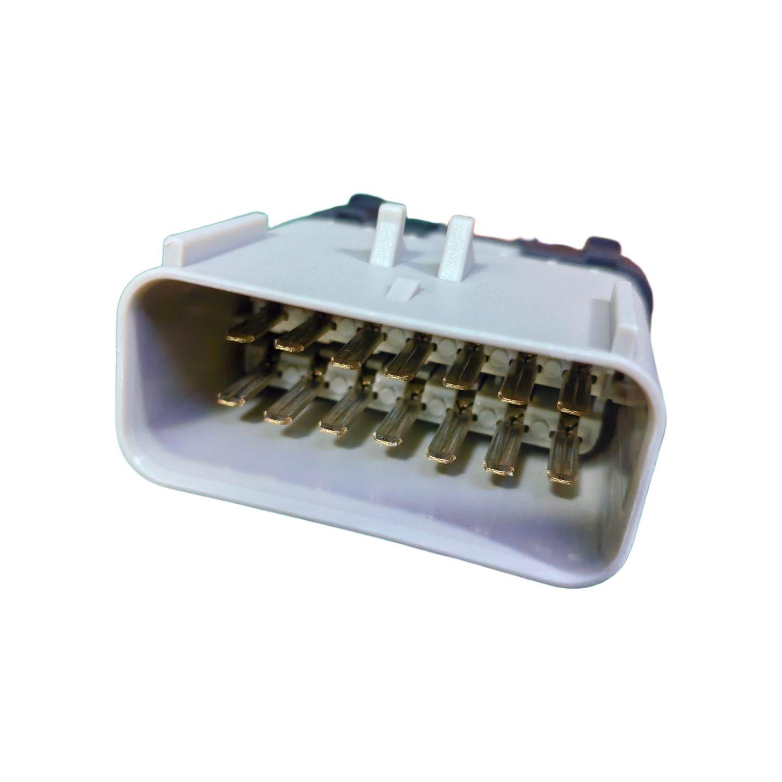
The connector geometry used on light vehicles is a trapezoidal housing with two rows of eight contact positions and a keyed outline that prevents a reversed insertion. Alignment posts and the housing key are part of that geometry, so a plug and a socket from different keying positions are not intended to mate. The physical interface is described in SAE J1962; diagnostic services and test modes are covered separately in SAE J1979. We reference those documents for terminology only. This page makes no statement of conformity to either document, and no statement about the diagnostic functions of the equipment the cable connects to.
What matters to the cable builder is that the geometry fixes the housing and contact layout but not the wiring. Several positions are assigned by the vehicle or equipment designer, and a port can carry both communication circuits and a permanent supply. We therefore never infer a pin assignment from the connector shape, from wire color, or from a listing for a similar lead. The approved drawing states which position carries which function and how the supply conductors are protected. Our comparison of diagnostic connector families gives the wider context for that distinction.
How to Specify an OBD2 16-Pin Pigtail Harness
A quotation starts with six items. State the connector gender and keying, and whether you want an overmolded plug, an assembled housing or a female socket. Attach a pinout table that maps every used contact position to a function, a wire color and a gauge. Describe the far-end termination, including strip length and any terminal part numbers. Choose the jacket compound, shielding and cable outer diameter, then give the finished length, the exit direction and any marking or labeling. Finally state the quantity and whether the build is a prototype or a volume run, confirm per RFQ.
A sample harness shortens this considerably. Where a connector already exists in your equipment, we match the gender, keying and contact plating to it; where the equipment is new, we take those details from the connector datasheet you specify. The RFQ preparation guide lists the same items in checklist form. Anything not fixed on the drawing is quoted rather than assumed, confirm per build.
Reference Build and Items Confirmed per Build
The table below is the configuration we quote from, not a fixed part number. It deliberately leaves electrical values, dimensions and approvals open, because those come from the connector datasheet and the equipment design. Everything not listed is quoted rather than assumed.
| Item | Reference configuration |
|---|---|
| Connector interface | 16-position, two rows of eight, diagnostic link connector geometry |
| Contact gender | Male pin plug or female socket with contact insert; confirm per build |
| Keying and alignment | Housing keying and alignment posts as shown on the approved drawing |
| Available end styles | Overmolded plug, assembled housing, or female socket with flying leads |
| Far-end termination | Stripped, tinned, crimped terminals or a customer-specified connector; confirm per build |
| Pin assignment | Full pinout table supplied by the customer; no position assumed |
| Wire gauge and colors | Set on the drawing; conductor count and color code confirm per build |
| Jacket compound | PVC, PUR or TPE; flame and smoke requirements confirm per build |
| Shield and drain | Shielded or unshielded construction; shell termination confirm per build |
| Cable length and exit | Cut to the drawing, straight or right-angle; confirm per RFQ |
| Strain relief | Backshell, overmold or adhesive-lined sleeve; confirm per build |
| Electrical rating | Set by the equipment design and connector datasheet; not published here |
| Test plan | 100 percent continuity, pinout and insulation check; limits confirm per build |
| Order quantity | Prototype 1-50 pieces; volume from 500 pieces; confirm per RFQ |
Pinout Discipline for Open Wire Ends
A molded adapter has its wiring fixed at the factory; an open-wire lead puts that decision in the hands of the installer, which is useful and also unforgiving. A diagnostic connector can carry communication circuits alongside a permanent supply, so crossing two conductors at the far end can damage the equipment under test. We ask for a pinout table rather than a wire color list, because color codes are not consistent across vehicle programs or harness suppliers. The equipment designer owns fusing, short-circuit protection and the decision about which positions are powered.
Before any cutting starts, the drawing is checked for contact count, gender and keying, then the first article is verified position by position against that drawing. Where a shield is specified, the drawing states whether it terminates to the shell or to a dedicated contact, and whether it is cut back at the far end. These are construction details, not suggestions; a lead built without them is not the same part. Test limits are confirm per build.
Overmolded Plug, Assembled Housing, or Female Socket
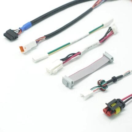
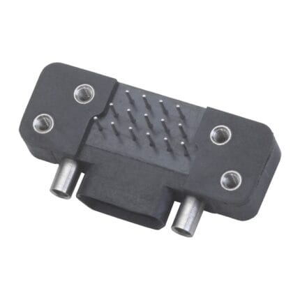
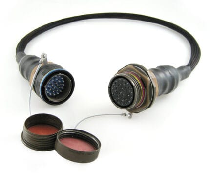
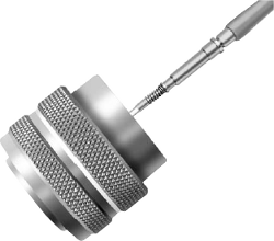
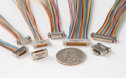
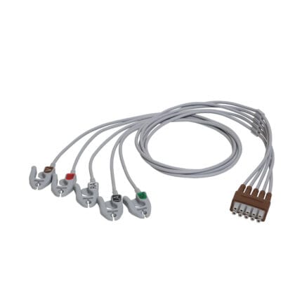
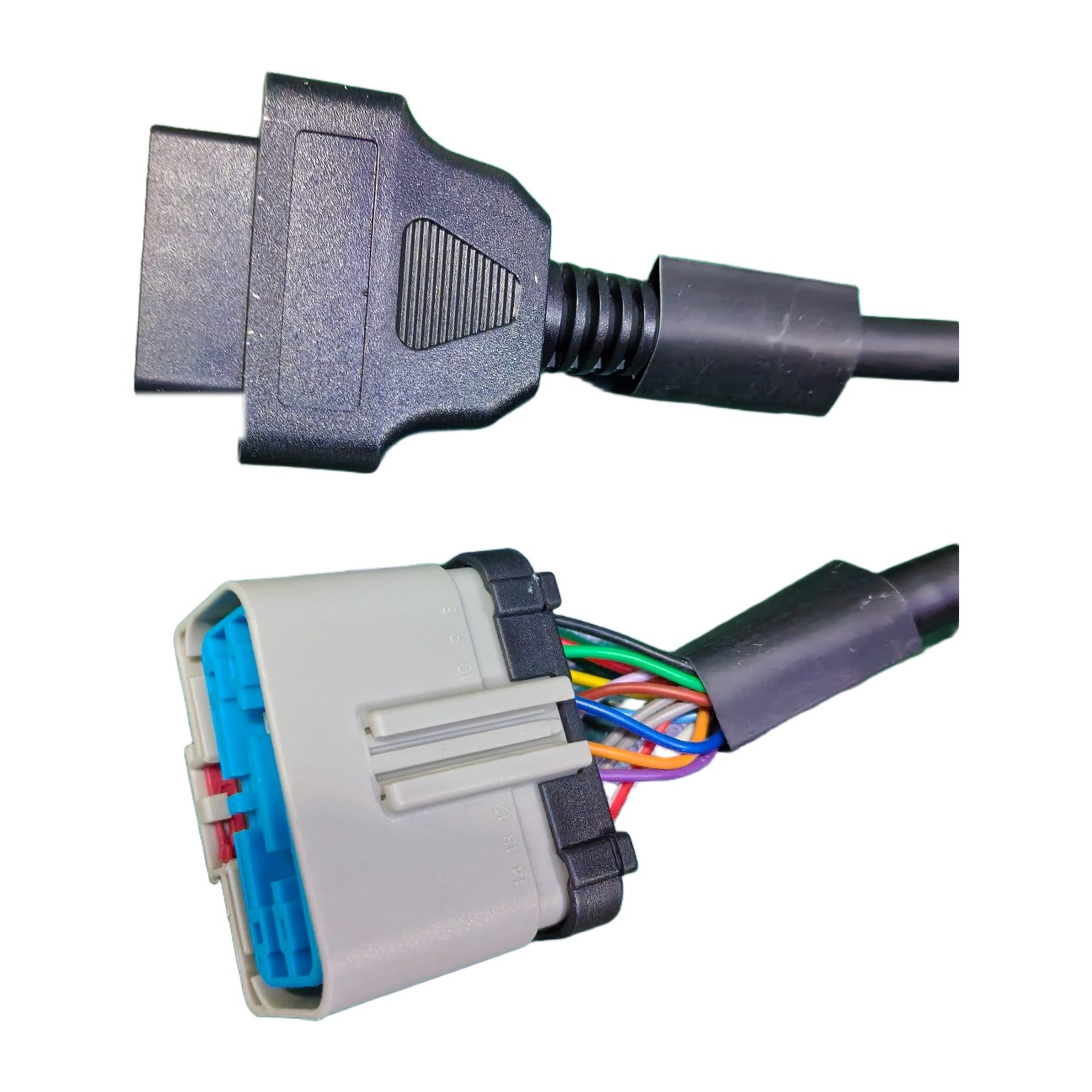
Three end styles cover most requests. An overmolded plug is a one-piece molded body around the connector and cable exit, chosen when the lead is handled often and a consistent strain relief matters more than field serviceability. An assembled housing uses separate shell halves, a colored terminal insert and a secondary lock; it is easier to rework on a bench and is common on prototype builds. A female socket with flying leads suits equipment that needs a diagnostic port mounted to its own panel or bracket. The photographs on this page show a molded plug, a male pin face and a socket with terminated leads.
We do not treat these styles as interchangeable on a single drawing. Each has a different cable outer diameter range, exit geometry and assembly sequence, and an existing tool may suit one but not another. Gender, keying and contact plating are read from the connector datasheet for the selected part. Which style ships, and whether an existing mold can be reused, are confirm per RFQ. The overmolded assembly guide explains the one-piece option in more detail.
Conductors, Jacket and Strain Relief
Conductor count follows the drawing, not the contact count: unused positions stay unpopulated unless the drawing says otherwise. Stranded copper is standard, with gauge and color set per position. Jacket compound is chosen for the installed environment: PVC for general cabinet and bench wiring, PUR where abrasion and repeated flexing dominate, TPE where a softer hand or a wider temperature window is needed. Flame, halogen and smoke requirements are specified for the build with their test documentation, not claimed generically for a material family.
Cable outer diameter has to sit inside the range the selected backshell or overmold can capture, so it is checked at the quoting stage. Where a sleeve is fitted over the connector-to-cable transition, an adhesive-lined dual-wall tube can serve as strain relief and as a rear seal; a plain single-wall tube mainly provides abrasion protection. Neither tube carries an environmental rating of its own, and we publish no ingress class for the finished lead. Length, exit direction and any right-angle requirement are confirm per RFQ.
Typical Applications
Test benches and ECU development. An open-wire lead is the usual choice when a bench fixture or a development ECU needs a diagnostic port but has no fixed mating connector yet. The 16 conductors land on terminal blocks or a breakout board, and the pinout can change between prototype revisions without retooling a molded end. We cut and mark the leads to the drawing for each revision, so a wiring change stays a drawing change. Bench use also means frequent reconnection, so the strain relief at the connector exit is specified with that duty in mind. All electrical limits remain confirm per build.
Fleet and telematics prototype wiring. Prototype vehicle installations often need a short lead from the diagnostic port to a data logger or a power tap, with the far end finished to suit the device being fitted. A pigtail lets the installer terminate that end in the vehicle rather than carrying a fixed adapter for every device. Which conductors are powered, how they are protected and how the harness is routed are decisions for the vehicle integrator; we build the interconnect to the drawing and do not publish vehicle compatibility lists. Cable jacket, length and marking are confirm per RFQ.
Service leads and harness repair. A damaged diagnostic lead or a worn connector housing can be replaced with a build-to-print assembly that matches the original pinout and exit direction. We ask for the old harness as a sample where possible, because wire color codes and keying vary between vehicle programs even when the connector geometry looks the same. The replacement is verified for continuity and pinout before it leaves the bench. Any required documentation or approval for the installed system stays with the equipment builder, confirm per build.
These are application contexts for the interconnect, not claims about the equipment that uses it. We build cable assemblies; we do not design the machine and we do not certify the finished system. If your application carries a specific approval, environmental or documentation requirement, put it in the RFQ so the quotation and the test plan cover it, confirm per build.
Installation and Handling Notes
Confirm the pinout against the drawing before the open ends are landed, and make sure the equipment is not powered during that step. If the connector end is an assembled housing, check that the terminal insert and secondary lock are fully seated before mating, and that the rear shell clips are closed. Route the cable so a service loop, not the termination, takes any pull, and keep the minimum bend radius of the chosen jacket in mind when an enclosure is closed. Fit a dust cap whenever the connector is unmated.
Where an adhesive-lined sleeve is used at the rear entry, clean the jacket, match the shrink ratio to the largest and smallest substrate, allow enough overlap and heat evenly until adhesive is visible at both ends. Overheating can damage the jacket and underheating leaves the adhesive inactive; either condition breaks the very seal the sleeve was meant to provide. These are process controls we put in the work instructions for the build, confirm per build.
Custom Builds and Ordering
Prototype quantities of 1-50 pieces are quoted for fit checks and field trials; volume production starts from 500 pieces. Both are built to the same approved drawing, and a sample from an existing harness is the fastest way to fix the pinout and the physical details. We have built more than 3,000 tooling sets since 2012 and keep over 100 active molds, so many exit geometries and overmold shapes can be reused; whether an existing tool fits your connector is confirm per RFQ.
The RFQ preparation guide lists what to send. Open a written quote through the RFQ form. Prices, lead times and any minimum order variation are confirm per RFQ; this site does not publish a price list.
Quality, Testing and Compliance
Every assembly is checked for continuity, pinout correctness and insulation before it leaves the bench, with the pass limits set on the approved drawing. A first article from each build is compared position by position with the pinout table. Where the drawing calls for a specific environmental or mechanical test, the test is quoted and documented for that build rather than asserted from a connector datasheet. Material declarations and any third-party documents are available on request when they apply to the components actually used, confirm per build.
We keep the distinction between component data and assembly claims explicit. A connector datasheet supports statements about that connector; it does not by itself support a statement about our finished cable. If a buyer needs a particular certificate or test report for the whole assembly, that requirement is agreed before production so the documentation matches what ships.
Frequently Asked Questions
What does pigtail or open wire ends mean on this build?
One end carries the 16-position diagnostic connector and the other end is left as individual conductors rather than a second molded plug. The leads can be stripped, tinned, fitted with crimped terminals or terminated into a connector you specify. That lets the cable land on a terminal block, a test fixture or an ECU harness without an adapter chain. The exact treatment is set on the drawing, confirm per RFQ.
Can I define the pinout and wire colors?
Yes, and we ask you to. Send a pinout table that gives every contact position its signal or supply function, wire color, gauge and any shield termination. We build to that table and verify it electrically before shipment. We do not infer a pin assignment from the connector standard, because several positions in a diagnostic port are left to the equipment designer.
Is this a diagnostic scan tool?
No. This product is a cable assembly, not a scan tool, a protocol converter or a software interface. It provides the mechanical and electrical connection defined by your drawing. Which controllers can be reached, and with which software, depends on the diagnostic equipment and the vehicle, not on the cable. We make no claim about protocol support or vehicle compatibility.
What do you need to quote an OBD2 16-pin pigtail harness?
Send the connector gender and keying, the pinout table, the far-end termination, wire gauge and color code, jacket and shielding, cable length and exit direction, and the target quantity. A sample harness or an existing drawing is the fastest route. All ratings, lead times and any documentation requirements are confirm per RFQ.
Related Cable Ranges
This build sits in our Automotive Cable and Wire Harness range. For branched builds to a drawing see Custom Wire Harnesses, and for multi-conductor signal work see Signal and Data Cables. Related diagnostic and pigtail leads already on the site include the DT connector pigtail harness, the 16-pin J1962 female to ECU board harness, the OBD2 flat extension cable, the J1939 to OBD2 diagnostic cable and the OBD2 Type B cable. Send your drawing through the RFQ form.
| Connector interface | 16-position, two rows of eight, diagnostic link connector geometry |
|---|---|
| Contact gender | Male pin plug or female socket with contact insert; confirm per build |
| Keying and alignment | Housing keying and alignment posts as shown on the approved drawing |
| Available end styles | Overmolded plug, assembled housing, or female socket with flying leads |
| Far-end termination | Stripped, tinned, crimped terminals or a customer-specified connector; confirm per build |
| Pin assignment | Full pinout table supplied by the customer; no position assumed |
| Wire gauge and colors | Set on the drawing; conductor count and color code confirm per build |
| Jacket compound | PVC, PUR or TPE; flame and smoke requirements confirm per build |
| Shield and drain | Shielded or unshielded construction; shell termination confirm per build |
| Cable length and exit | Cut to the drawing, straight or right-angle; confirm per RFQ |
| Strain relief | Backshell, overmold or adhesive-lined sleeve; confirm per build |
| Electrical rating | Set by the equipment design and connector datasheet; not published here |
| Test plan | 100 percent continuity, pinout and insulation check; limits confirm per build |
| Order quantity | Prototype 1-50 pieces; volume from 500 pieces; confirm per RFQ |