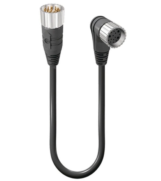
M23 16+3 Hybrid Servo Cable, Power + Signal, IP67
This m23 hybrid servo cable carries power and feedback in one connector: the hybrid insert combines sixteen power contacts with three signal contacts, so a servo motor gets its drive current and its encoder signals through a single sealed cable run.
Overview
This m23 hybrid servo cable carries power and feedback in one connector: the hybrid insert combines sixteen power contacts with three signal contacts, so a servo motor gets its drive current and its encoder signals through a single sealed cable run.
Hybrid M23 inserts exist to cut cable count on servo axes: instead of one thick power line and a separate feedback line sharing the same drag chain, the 16+3 layout carries both circuits through one connector and one jacket. That halves the chain fill, removes a mating operation at every service, and keeps the power and signal pins inside a single keyed shell so the pair cannot be plugged into the wrong housing.
Key Specifications
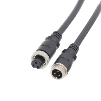
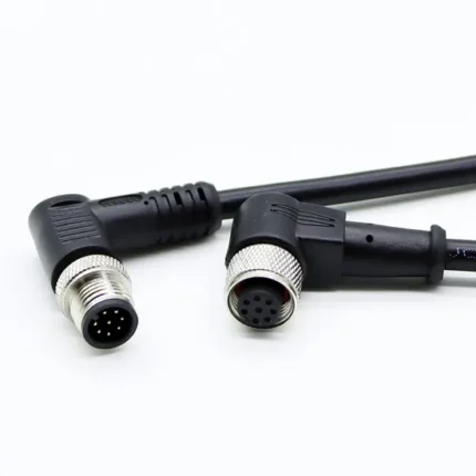
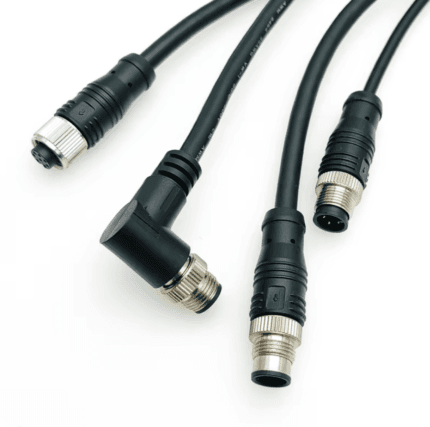
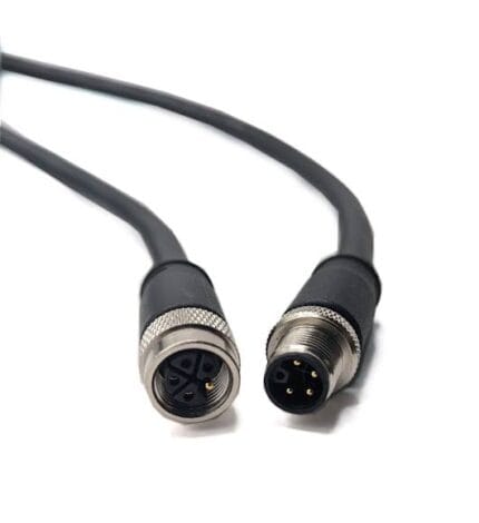
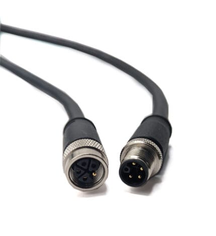
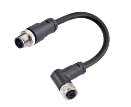
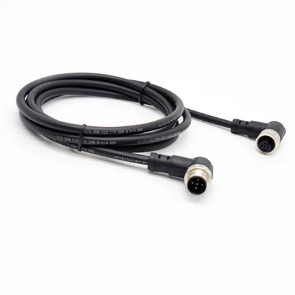
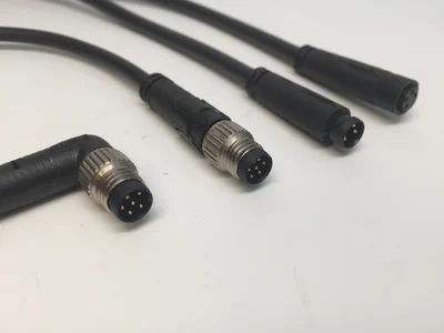
The table below lists the configuration shown in the product photo.
Why a Servo Axis Needs Two Circuits
Every closed-loop axis runs two conversations at once. The drive sends current down one set of conductors to make the motor produce torque, and the feedback device on the motor shaft reports position, speed or commutation state back along another set. The two jobs have almost nothing in common. Power wants contact area and conductor cross-section. Feedback wants quiet: encoder and resolver signals live at levels where even modest interference arriving inside the same jacket shows up as position error, hunting, or a drive trip that appears and disappears with machine load.
Keeping those two worlds separate while still running them through one shell is the whole engineering problem behind a hybrid insert, and it is why hybrid layouts are built around physical separation inside the insert rather than simply packing every contact into one ring.
How This Layout Sits in the M23 Family
The M23 shell is used across three broad insert families, and knowing which one a machine was built around is the first step in specifying a replacement cordset. Power-only inserts use a small number of large contacts sized for motor supply. Signal-only inserts use many finer positions for encoder, resolver, brake and winding-temperature circuits; 12- and 17-position layouts are the common ones. The hybrid class carries both contact sizes together in one insert, which is the arrangement here.
That family structure matters at the machine because the keyways that prevent wrong mating also mean the classes do not interchange. A hybrid plug will not seat in a signal-only receptacle, so replacing a two-cable installation with a single hybrid run means changing both ends of the circuit, not just the cordset.
Construction and Materials
The hybrid insert is crimp-terminated and sealed into the metal shell, with the power and signal contact rows separated inside the insert to keep coupling noise away from the feedback lines. A 360-degree shield termination surrounds both circuits, the knurled coupling nut seats with a positive thread lock, and the overmolded strain relief holds the round industrial jacket through drag-chain flexing. The right-angle female exit keeps the bend radius outside the connector on motors whose ports face a mounting shoulder.
Conductors are finely stranded and selected against the duty you declare, because the flex life of a moving run depends far more on strand construction and bend radius than on anything in the datasheet headline. Tell us whether the cable is a static cabinet run, a drag-chain duty cycle, or a torsion application on a rotating joint, and the conductor and jacket are built to that regime rather than to a generic specification.
Shield termination is treated as part of the assembly rather than a finishing step. The braid is clamped around its full circumference at the shell instead of being gathered into a drain wire, which is what keeps the screen effective at the connector rather than just along the middle of the cable.
Typical Applications
Machining centers are the classic home for this insert: spindle drives and feed axes where the motor sits inside a chip-and-coolant enclosure and every extra penetration through the panel is another place for contamination to enter. Consolidating power and feedback into one coupling removes one gland and one entry point per axis.
On articulated robots the argument is chain fill rather than sealing. Joint drives route through tight, continuously flexing harnesses where space is rationed by the link casting, and reducing two round cables to one buys room for the air lines and dress packs that compete for the same channel.
Packaging machines, pick-and-place units and indexing tables use these hybrid builds when axes are distributed around a frame and each one would otherwise need separate home runs back to a cabinet. Printers and converting lines adopt them for similar reasons on driven cylinders and registration axes, where the feedback signal has to stay clean next to high-current motor leads in the same tray.
Precision positioning stages used in semiconductor handling, dispensing and automated inspection are the demanding end of the range: high-resolution feedback, small dimension tolerances, and no tolerance for a position error traceable back to the cable.
The same interface appears in renewable energy and other hostile environments, where a sealed threaded shell, a wide-operating-temperature jacket and an assembly rated for continuous vibration matter more than any single electrical figure.
Choosing Between Hybrid and Two-Cable Builds
A single-cable hybrid build wins on axis count, chain space and service time, and it eliminates the classic commissioning mistake of powering a motor with its feedback still unplugged. It is the right choice on new machine designs and on any retrofit where both ends of the circuit can be converted together.
Two separate cables remain the better answer where an existing machine already has matching power and feedback ports that you want to keep, where the power section needs to be swapped independently of feedback during maintenance, or where the drive and encoder documentation give genuinely different cable classes for the two circuits. If the pin map does not exist in one document covering both groups, stay with the two-cable arrangement.
Compatibility and Fitment
The shell, thread and hybrid insert follow the M23 platform dimensions used across industrial drive brands; insert pinouts differ between drive and encoder manufacturers, so match the pin map in your drive documentation before ordering. Confirm the gender and exit direction against your motor connector; the hybrid insert does not interchange with signal-only or power-only M23 inserts.
Send us the two ends of the circuit you have. Where the motor carries a standard hybrid receptacle and the drive uses a D-sub debug or feedback port, we terminate the second end to suit rather than forcing an adapter into an untidy panel.
Installation and Handling Notes
Route the hybrid run so that it is not sharing a duct exclusively with high-current mains or welding supply if the axis also depends on fine feedback resolution; separation by routing costs nothing and is easier to get right before the machine ships than after.
Support the cable close enough to the connector that the strain relief is not carrying the weight of the span, and observe the bend radius on any right-angle exit, since the exit direction here exists specifically to keep that bend outside the shell.
Custom Builds and Ordering
Pin assignments, cable classes, lengths and exit directions are produced to order. Send the drive and encoder datasheet pages and we will crimp and test to the exact hybrid pin map. Prototype and sample lots run from 1 to 50 pieces; production orders start at 500 pieces per part number.
Packaging and Shipping
Each cable ships bagged with protective caps over the insert; OEM labels and reel packing are available.
Quality and Compliance
Every contact is continuity and pin-map tested before shipment, power and signal circuits are checked separately, and shield termination resistance is verified on the assembly. See the IEC 61076-2-102 M23 connector standard for the governing interface specification.
Material declarations against RoHS and REACH are issued per project, alongside the dimensional and electrical reports agreed at quotation; see certifications, compliance and material declarations. Where your drawing names a UL style or another approval, the build follows your drawing and ships with the supporting document rather than a claim of our own. For continuous motion the stranding, lay length and jacket are built to the flex method described under high-flex drag chain harness builds, with the cycle count defined in the test scope. More background: what automation programs ask for. Tooling for this build is cut in our own tool room and belongs to your program, so a repeat run years later starts from the same tool.
Frequently Asked Questions
Can I use this to replace two cables on an existing machine? Only if both ends carry hybrid M23 interfaces. If the motor has separate power and feedback ports, the correct replacement is two cordsets.
Is the shield carried through both circuits? Yes. The 360-degree screen encloses the full assembly, which is what allows power and low-level feedback to share one jacket.
What if the drive-end termination is not M23? Mixed builds are routine. Give us the drive port type and we terminate that end to match, keeping the motor-end hybrid connector as specified.
Related Cable Ranges
Browse the related ranges: Circular M-Series Cable Assemblies Signal and Data Cables Screw-Lock Molded Cable.
The remaining feedback side of a servo axis is covered by the M23 17-pin encoder feedback cable, while machines that keep power and feedback on separate runs use the M23 encoder feedback cable.
| Connector | M23 hybrid cable connector, 16+3 insert |
|---|---|
| Contacts | 16 power + 3 signal (hybrid insert) |
| Orientation | Straight male to right-angle female |
| Coupling | Threaded metal nut |
| Shielding | 360-degree overall shield |
| Ingress Rating | IP67 when mated |
| Application | Servo motor power and feedback in one run |